

We developed an application Probe Screen for more convenient work with the touch probe in LinuxCNC. Description and source codes are presented in this article for version V1. Description of the new version V2 is here.
![]() Attention! Measuring operations are very intolerant of incorrect settings. It is strongly recommended to do preliminary tests on loose object that will not damage the probe when unexpected movements. It is recommended to carefully check each setting before measuring the workpiece.
Attention! Measuring operations are very intolerant of incorrect settings. It is strongly recommended to do preliminary tests on loose object that will not damage the probe when unexpected movements. It is recommended to carefully check each setting before measuring the workpiece.
Installation
...more (horizontal scrolling ON)
1. Add to your .ini these settings
......
[DISPLAY]
DISPLAY = axis
EMBED_TAB_NAME=Probe Screen
EMBED_TAB_COMMAND=halcmd loadusr -Wn gladevcp gladevcp -c gladevcp -u python/probe_screen.py -x {XID} probe_icons/probe_screen.glade
......
[RS274NGC]
FEATURES=30
SUBROUTINE_PATH = macros
......
[TOOLSENSOR]
# Control probe rapid feed
RAPID_SPEED = 600
2. The following files from the archive are placed in:
your-folder-configuration/pyton
probe_screen.py
your-folder-configuration/macros
all from folder "macros"
your-folder-configuration/probe_icons
all from folder "probe_icons"
home folder ~/
.axisrc
If you are already using .axisrc, then only add to your file contents of this .axisrc
If something went wrong and you need debugging, here is a list of variables that are used in the settings, you can find them in the files macros/*.ngc and python/probe_screen.py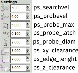
↑ roll up
Measurement
Set the probe in the spindle.
Move manually probe for Z about 2-10 mm above the workpiece surface,
and for XY about the position indicated by the colored dot on the appropriate button Probe Screen.
Fill parameters. Meaning of the parameters should be clear from the names and pictures (the name pop up when approaching the mouse, more..). If you change the parameters are automatically saved in .pref .
![]() Hit only! the button that corresponds to the position of the probe above the workpiece. For the other buttons - another position above the workpiece.
Hit only! the button that corresponds to the position of the probe above the workpiece. For the other buttons - another position above the workpiece.
![]() If you change the values of the parameters using the keyboard (and not with the mouse on the arrows), you must press Enter to commit the new values.
If you change the values of the parameters using the keyboard (and not with the mouse on the arrows), you must press Enter to commit the new values.
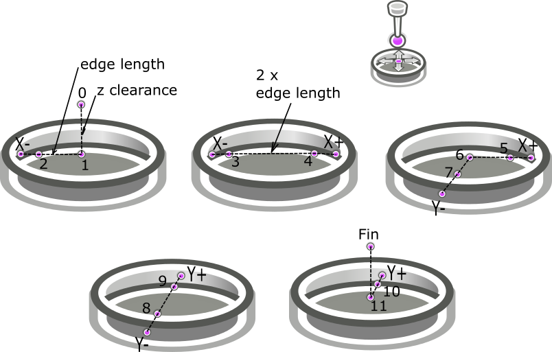
The trajectory of the probe by the example of measurement outside corner X+Y+
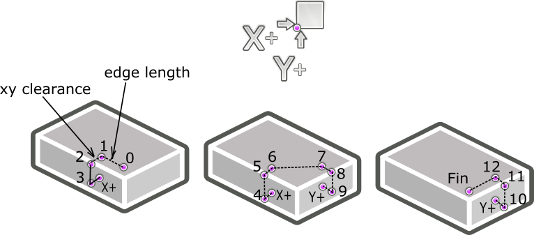
Two separate searches are combined: X+ and Y+.
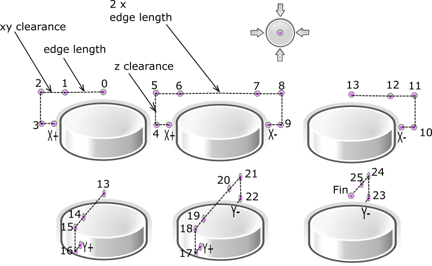
Central, the most complex button, starts a row 4 searches X+ X- Y+ Y-, edge length should be approximately equal to the radius of the cylinder, xy clearance indented outwardly from the cylinder wall (it is necessary to compensate for the error of the approximate initial manual exposure of the center and add the radius of the tip of the stylus)
Trajectory of motion of the centroscope using the example of measurement of an internal angle X+Y+
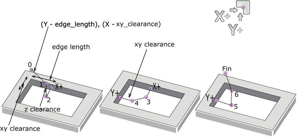
The search for the hole center is constructed as follows X- X+ Y- Y+, edge length should also be approximately equal to the radius of the hole being measured, xy clearance offset from walls of the hole to the center (it is necessary to compensate for the error of the approximate initial manual exposure of the center and add the radius of the tip of the stylus).
Any of the searches is completed by moving XY to the desired point (either the edge, or the angle, or the center), Z remains in the original position. The found point can be automatically made by zero or a specific number.
How to use Rotation:
We set the probe above the desired edge 2-4 mm (the approximate position shows the colored dot on the button). Fill in the parameters. Press only! corresponding to this position button.

Then there will be two measurements, as indicated by the arrows on the button.
The parameters are set so
edge length = distance between measured points
xy clearance = offset from the edge
z clearance = embedment
Auto Rott:
-if Yes, then after measuring the coordinate system will automatically rotates by the measured angle,
-if No, then the angle is simply measured and written out.
The angle is calculated relative to the X axis for the front and back faces, relative to the Y axis for the right and left faces.
After the coordinate system has been rotated, all other measurement groups will start working in a new coordinate system.
You can also rotate the coordinate system at an arbitrary angle manually - type an angle in the New angle field and click the button to approve.