We developed the application Probe Wizard for convenient work with the touch probe and the toolsetter in Mach3. The article contains instructions for installation and use. Link for downloading the application (open sources) - at the end of the article.
![]() The Probe Wizard application is not necessary for working with our sensors and is not supplied with sensors; you can use this and any available and suitable software with our sensors. On the other hand, the Probe Wizard can be used with third-party sensors. This application is free software; you can redistribute it and/or modify it under the terms of the GNU General Public License as published by the Free Software Foundation; either version 2 of the License, or (at your option) any later version. This application is distributed in the hope that it will be useful, but WITHOUT ANY WARRANTY; without even the implied warranty of MERCHANTABILITY or FITNESS FOR A PARTICULAR PURPOSE. See the GNU General Public License for more details.
The Probe Wizard application is not necessary for working with our sensors and is not supplied with sensors; you can use this and any available and suitable software with our sensors. On the other hand, the Probe Wizard can be used with third-party sensors. This application is free software; you can redistribute it and/or modify it under the terms of the GNU General Public License as published by the Free Software Foundation; either version 2 of the License, or (at your option) any later version. This application is distributed in the hope that it will be useful, but WITHOUT ANY WARRANTY; without even the implied warranty of MERCHANTABILITY or FITNESS FOR A PARTICULAR PURPOSE. See the GNU General Public License for more details.
![]() Attention! Measuring operations are very intolerant of incorrect settings. It is strongly recommended to do preliminary tests on loose object that will not damage the probe when unexpected movements. It is recommended to carefully check each setting before measuring the workpiece.
Attention! Measuring operations are very intolerant of incorrect settings. It is strongly recommended to do preliminary tests on loose object that will not damage the probe when unexpected movements. It is recommended to carefully check each setting before measuring the workpiece.
Installation
1. The folder Probe Wizard EN from the archive put inside the folder
⁄Mach3 ⁄Addons
2. All files from the /macros folder from the archive should be placed inside the macro folder with their own machine profile, by default this is
⁄Mach3 ⁄macros⁄Mach3Mill
Using.
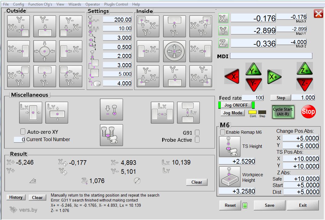
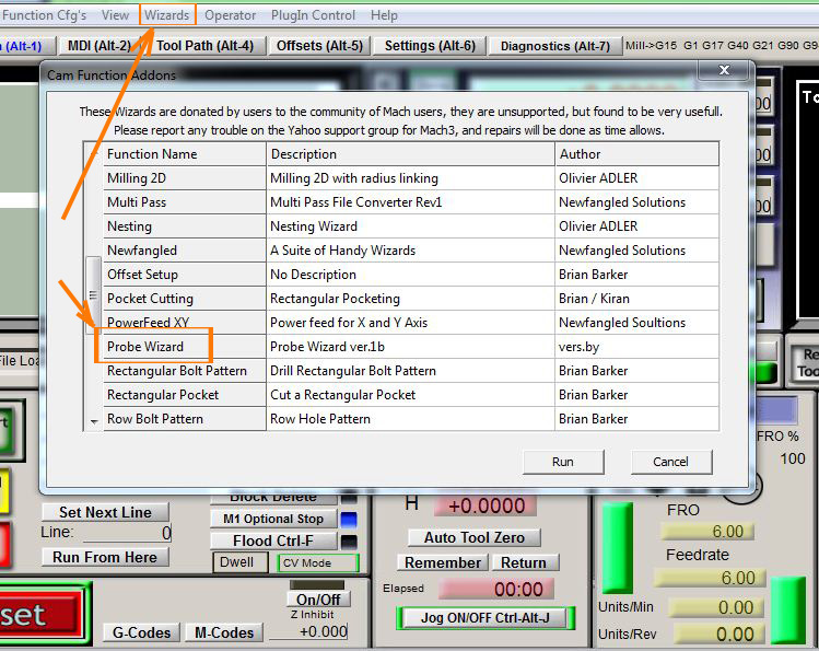
You can start the application from the menu Wizards -->Pick Wizard...-->Probe Wizard
The probe is mounted in the spindle. Bring in manual mode approximately 2-4 mm (see below "Search distance") in Z above the surface of the workpiece, and in XY approximately in the position indicated by the ccolor point on the corresponding button of the Probe Wizard. Fill the parameters:
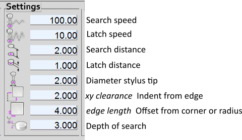
Search speed: “fast” feed rate at which the probe searches for the target workpiece in machine units per minute. As soon as touched, it retreats to the distance indicated in the fourth field, and then again searches at a slower Latch speed (indicated in the second field). This is done to eliminate inaccuracies caused by the inertia of the machine, just as Mach3 handles home switches. The search speed should be slow enough to give you an acceptable initial accuracy, but fast enough to not waste time waiting for movement. Recommendation: 200-500 mm / min.
Latch speed: The "slow" speed that the machine uses for accurate measurement. This speed depends on how quickly your machine stops when the probe is triggered. The value of this field should be small enough for the machine to instantly stop when moving at such a speed. You must experiment with it to find the greatest value that does not sacrifice accuracy with your center finder. Recommendation: 5-50 mm / min.
Search distance: this is the maximum limit on how far the probe will search for a target. If the search distance is too short, you will receive a message like "G31 finished without probe trip". For safety reasons, it is recommended to set this parameter no more than free running of the stylus of the probe: 3-4mm.
Latch distance: this is indented to perform a re-search. This is a short distance (short because it will need to be passed at a "slow" Latch speed), but large enough for the probe to stop touching the part and bring it to the search ready state. If you make the Latch distance too large, you will end up spending a lot of time waiting for the search to complete. Recommendation: 0.5-1mm
Diameter of stylus tip: Used for mathematical calculations of the coordinates of the search results. Theoretically, the probe tripped as soon as the ball touches the part, preventing further movement of the axis. Therefore, if you use a stylus tip with a diameter of 2 mm, you need to fix the coordinates of the machine 1 mm from the place where the sensor worked, and thus take into account the diameter of the tip. Half of the value that you enter in this field is subtracted or added to the place of drawdown of the probe (during the Latch search), depending on the direction of movement. If this number = 0, the resulting coordinates will be incorrectly shifted. It is worth using a micrometer to measure the tip of the stylus in order to add a size to this field, if the manufacturer has not told you.
XY clearance: this is the spare distance from the measured face (the same for X and Y, see diagrams below). It is necessary to compensate for the inaccurate manual positioning of the probe above the workpiece before starting the measurements. If this value is too small, you run the risk of ran into a part. XY clearance should be slightly larger than the radius of the stylus bulb. If it is too large, you lose time or run into another side of the part. Recommendation: stylus tip radius + 0.5 ... 1.5mm.
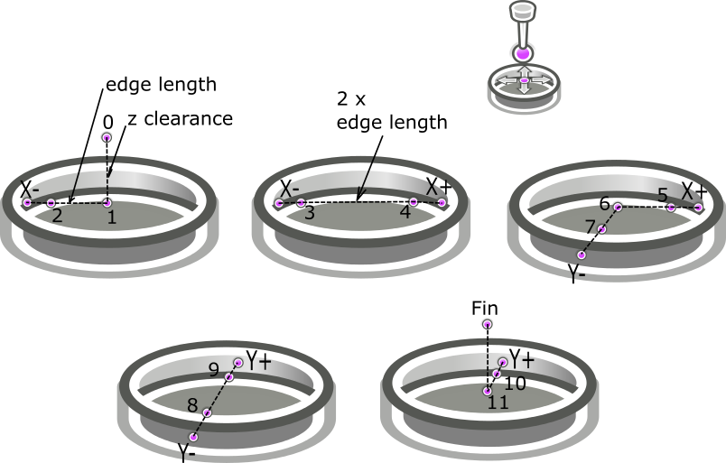
Edge length: This is the distance that some buttons use to determine how far to move at the quick speed of the machine (RAPID_SPEED) to the position before starting the search to speed up the work. For example, to find the center inside the hole, you manually set the probe within a short distance Z from the top of the hole (you can go directly into the hole, then Z clearance = 0) and approximately (by eye) in the center. The probe will go down by the value of Z clearance, then the X will move at a quick speed at (Edge length minus XY clearance). It then switches to the “search speed” indicated in the first field and starts the search sequence. In the case of this particular button (search for the center of the hole), Edge length must be set before the start of the search approximately equal to the radius of the hole. If the hole, for example, is about 8 mm, place the probe tip approximately centrally above it and about +1 mm Z. Edge length set = 4 mm, XY clearance = 2mm. Press the button, the probe goes down to the value of Z clearance (which in our case = 3, so the probe tip enters 2 mm into the hole) and moves 2 mm X- (Edge length 4 mm minus XY clearance 2 mm = 2 mm). Since we started approximately in the middle of the hole in X and Y, the action should position us within about 2 mm from the hole wall, which is good because it is nothing more than the maximum movement of the sensor (which in our case is the Search distance = 3 mm). The probe begins to move with a Search speed of no more than 3 mm to -X. Once triggered, the probe will retreat (+ X) at the Latch distance, slow down and then touch again. This will determine the location of the -X hole wall. After clarification, the probe will be installed on the opposite side of the hole again about 2 mm from the wall. The process is repeated here, as well as for Y + Y-.
If the Edge length is too large, the probe will abut the edge of the hole before it even starts searching. If this happens, the search will stop and give an error message. You will have to readjust your values, manually move the probe back to its original location and try again.
If the Edge length is too small, the probe may arrive at the desired starting position, but will not reach the hole wall when searching. If this happens, get another error. Correct the values, manually move the probe back to its original location and try again.
Recommendations:
-for the center (hole-cylinder) buttons the Edge length set approximately equal to the estimated radius (not to be confused with the diameter),
- for the corner buttons the Edge length is equal to the indent along the edge from the corner point,
-for the length buttons, set the Edge length approximately equal to half the length we are looking for (approximately equal to the radius of the inscribed circle),
-Edge length is not used at all in buttons for simple searches along one axis (X +, X-, Y +, Y-, Z-).
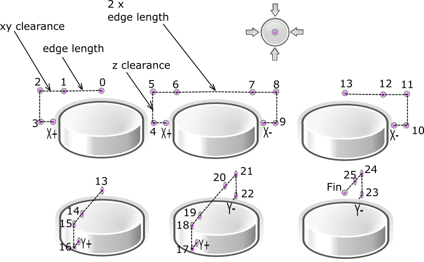
Z clearance (depth of search): this is the depth where the search will be conducted relative to the current position on Z. Z clearance is required for measurements Outside (left group of buttons). Example. If you set the Z clearance to 3 mm and position the probe >3 mm above the workpiece, then the search will not occur, because the stylus cannot touch the walls.
On the other hand, if you make this distance too large, the program will not check and will simply go into operation and may crash into the bottom of the hole.
![]() Use only! that button, which corresponds to the position of the probe over the workpiece. For another button, there is another position above the workpiece.
Use only! that button, which corresponds to the position of the probe over the workpiece. For another button, there is another position above the workpiece.
Picture below will show how xy clearance differs from edge lenght.
Trajectory of probe when measuring the external angle X+Y+
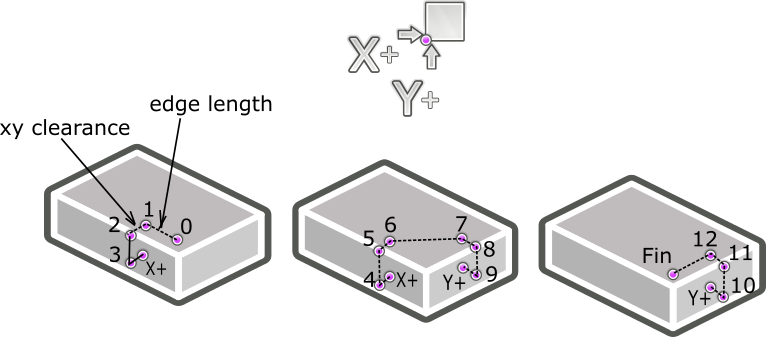
Two separate searches are combined: X+ и Y+.
Central, the most complex button, starts a row 4 searches X+ X- Y+ Y-, edge length should be approximately equal to the radius of the cylinder, xy clearance indented outwardly from the cylinder wall (it is necessary to compensate for the error of the approximate initial manual exposure of the center and add the radius of the stylus tip)
Trajectory of motion of the probe using the example of measurement of an internal angle X+Y+
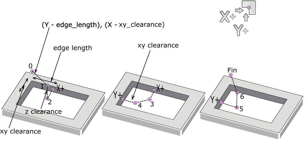
The search for the hole center is constructed as follows X- X+ Y- Y+, edge length should also be approximately equal to the radius of the hole being measured, xy clearance offset from walls of the hole to the center (it is necessary to compensate for the error of the approximate initial manual exposure of the center and add the radius of the stylus tip).
Any of the searches is completed by moving XY to the desired point (either the edge, or the angle, or the center), Z remains in the original position. The found point can be automatically made by zero or a specific number.
Settings for the tool measurement button:

The button starts the macro of measuring the diameter of the cutter on the toolsetter. Moves the spindle to the measuring point at a safe height, measures the height of the toolsetter's pad, then turns ON reverse rotation of spindle (it is recommended to set no more than 1500 rpm) and measures the diameter by analogy with the search for the center of the cylinder.
Constant parameters for a button are set by the user individually in a macro m924.m1s
' --------------------------------------------
' User's constants. Change for yourself.
' --------------------------------------------
Const ToolSetterDiameter =10 ' diameter of the measuring pad of toolsetter
Const SpindleReversRott =300 ' speed of reverse (M4) rotation of the spindle
' --------------------------------------------
Temporary parameters are set by the user individually in the "Settings" fields. The macro uses all the "Settings" fields, except the Search distance (taken from "M6") and Edge lenght (the radius of the measuring pad TS is taken), the "Diameter of stylus tip" field is used to enter the approximate diameter of the milling cutter), and in the field "M6": "TS Pos Abs" - XY coordinates of measuring platform, "Safe" safe height of movement, search downwards will start from the height of "Start".
Quick manual tool change (M6):
Probe Wizard allows you to speed up manual tool changes by automatically measuring the tool length during g-code execution. The user will only have to remove the old and install a new tool.
Requirement: presence of two sensors - touch probe and toolsetter.
Preparatory steps:
1.Toolsetter should be installed permanently on the edge of the desktop.
2. Set the workpiece on the table.
3. Insert the probe into the spindle.
4. Enter the parameters in the Probe Wizard, the parameters used by each button are highlighted in the figure. Parameters marked with blue circles are used by both buttons. The input position coordinates are machine
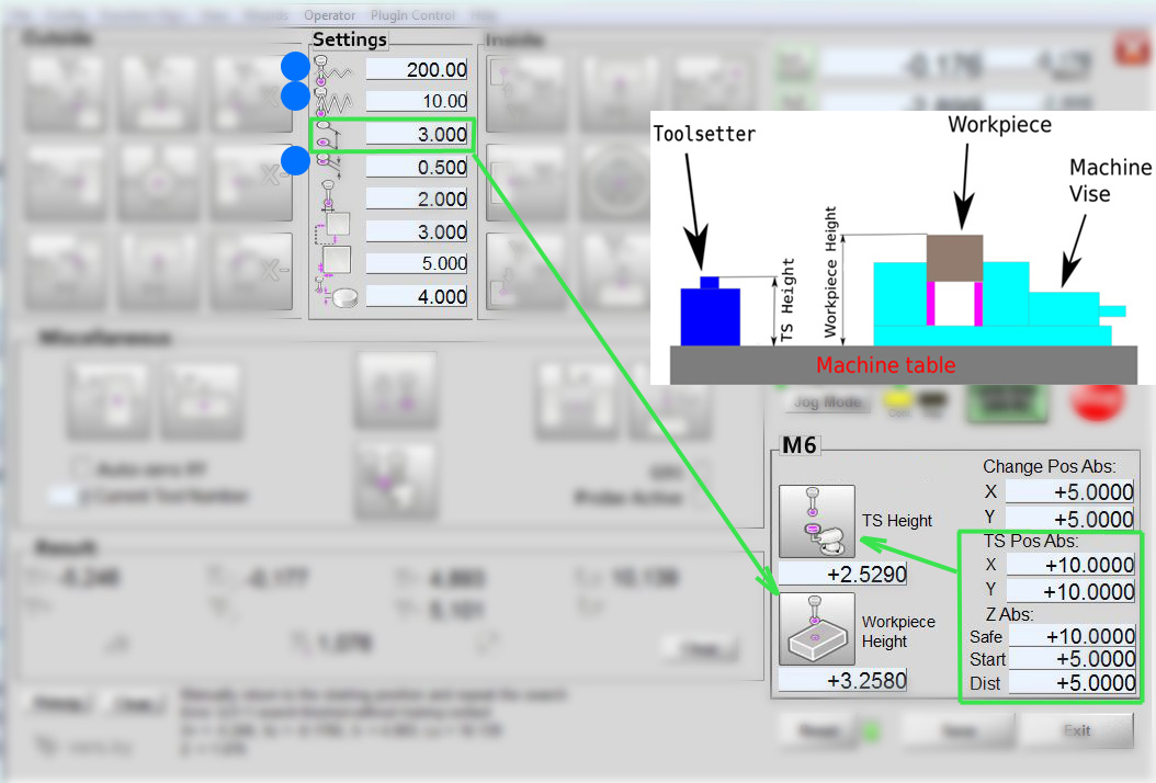
5. Measuring with a probe on the z surface of the measuring pad toolsetter: press the "TS Height" button, the probe will automatically perform the actions and the result will appear in the field under the button. The steps are as follows: the probe will move to the search point above the toolsetter at the coordinates specified in "TS Pos Abs", at the height of "Safe", the search will start down from the height of "Start", with a maximum distance of no more than "Dist". The search and refinement rates and the refinement distance will be taken from the “Settings” (marked with blue circles in the figure).
6. Measuring with a probe on the surface of the workpiece: the probe must be manually brought to the measurement site above the workpiece, press the “Workpiece Height” button, the probe will perform a simple search down from the current position, the result will appear in the field below the button. Search and latch rates and search and latch distances will be taken from the “Settings” (the top four parameters).
7.Enter the coordinates XY (abs.) of an arbitrary point at which it is convenient to change the tool "Change Pos Abs".
After this preparation, you can run the program g-code. As soon as the tool change command M6 Tn will encountered, the spindle will stop (in the Mach3 settings, the "Stop Spindle. Wait for Cycle Start" must be turned on) will move to the "Change Pos Abs", then the new tool is put, the Cycle is pressed Start "to continue, the new tool is automatically measured on the toolsetter, and g-code execution continues.
The quick manual tool change function uses the following macros:
"TS Height" - M926.m1s
"Workpiece Height" - M927.m1s
Remap M6 - M6Start.m1s, M6End.m1s
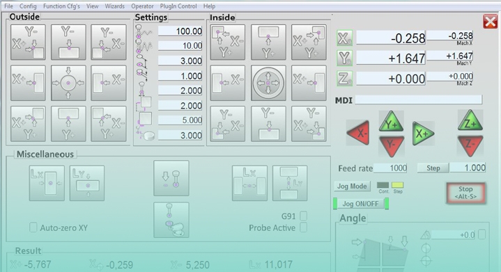
How to use Angle:
Activated by pressing the "TAB" key.
Set the probe above the desired edge 2-4 mm (the approximate position shows the colored dot on the button). Fill in the parameters. Press only! corresponding to this position button.
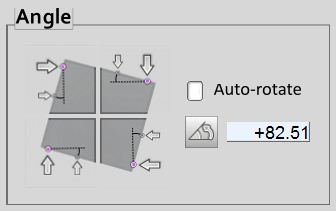
Then there will be two measurements, as indicated by the arrows on the button.
The parameters are set so
edge length = distance between measured points
xy clearance = offset from the edge
z clearance = embedment
Auto-rotate: (... soon...)
-if Yes, then after measuring the coordinate system will automatically rotates by the measured angle,
-if No, then the angle is simply measured and written out.
The angle is calculated relative to the X axis for the front and back faces, relative to the Y axis for the right and left faces.
After the coordinate system has been rotated, all other measurement groups will start working in a new coordinate system.
You can also rotate the coordinate system at an arbitrary angle manually - type an angle in the New angle field and click the button to approve.