
This User's Guide applies to the currently released Vers TSm v9 models. For earlier versions, the User's Guide can be found at this link.
Purpose.
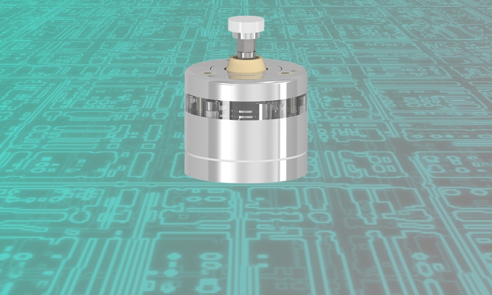
The Vers TSm sensor is used to determine tool height and diameter. CNC milling machine generates coordinates when the tool touchs the VersTSm measurement pad and uses them to calculate the height and diameter of the tool. The device can be used with various CNC systems: LinuxCNC, Mach3, embedded systems on industrial machines, etc.
Vers Tsm v9 main features
1. Unidirectional repeatability 0.001 mm.
2. Tungsten carbide pin-ball contacts.
3. Over travel limit 7mm.
4. Measuring tool length and diameter.
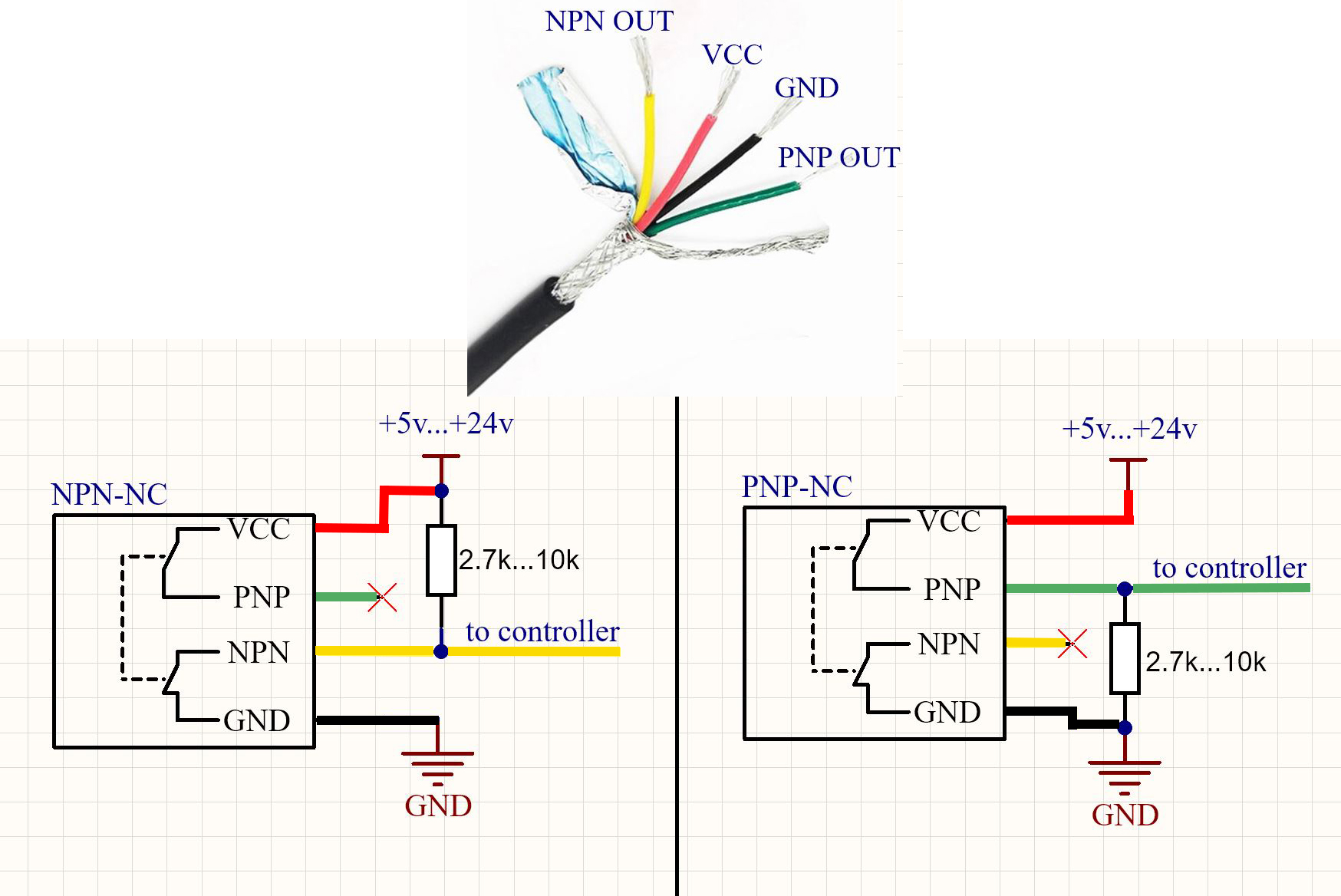
5. The tool setter is equipped with both NPN-NC and PNP-NC output types.
6. Protection against short circuits of the output to power or ground, from power reversal, splash protection.
Specifications.
Unidirectional repeatability | 0.001 mm |
Search directions | ±X, ±Y, -Z |
Over travel limit (X,Y,Z) | 7 mm |
Contact force | min 0.5N max 2N |
Diameter and overall height | D=34 mm, H=43 mm |
Diameter* and height of the ceramic pad | D=10mm, h=2.5mm |
Power supply | +5v...+24v |
Current сonsumption | <4mA |
Dust protection | Yes |
Splash protection | Yes |
Adjustability | Yes |
Possibility to measure tool diameter | Yes |
*Diameter 9.98 ±0.02mm, cylindrical and planar irregularity <2µm
Installation.
![]() Placement Vesr TSm is recommended to be chosen so that the entire surface of the ceramic platform of the device is in the working area of the machine, with an indent from the boundaries = the maximum diameter of the tool being measured + 2mm.
Placement Vesr TSm is recommended to be chosen so that the entire surface of the ceramic platform of the device is in the working area of the machine, with an indent from the boundaries = the maximum diameter of the tool being measured + 2mm.
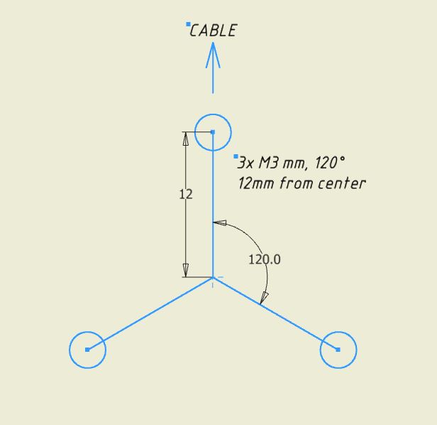
The device is fixed to the machine body with three M3 screws. Three threaded holes are prefabricated in the machine body:
Adjustment.
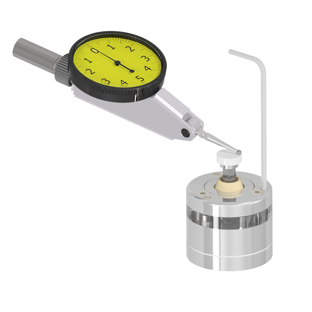
Before starting the measurement, it is necessary to adjust the device. As a result of the adjustment, the surface of the measuring platform should become parallel to the XY plane.
![]() The indicator should be sensitive to a weak effect of 0.3-0.5N (for example, most lever indicators have this property).
The indicator should be sensitive to a weak effect of 0.3-0.5N (for example, most lever indicators have this property).
For adjustment, three points are selected at the measuring pad approximately at the edge of the site in the direction of the adjustment holes. The stylus of the indicator is located to measure the deviations in height. The results of the indicator must have to the same values in these three selected points. For adjustment, a 2mm hex key is used from the kit, both screwing in and loosening of the adjustment screws located inside the holes, closed with elastic bands. The key is recommended to hold for a short lever, so as not to develop excessive force when screwing.
Connection.
Sensors are equipped with both types of outputs simultaneously. NPN-NC output on yellow wire, PNP-NC output on green wire
Using.
There is software ProbeScreen in free access for convenient work with probe in the LinuxCNC,
Probe Wizard - in the Mach3 system.