
User Guide
Purpose
The WL10 wireless rechargeable touch probe is designed to determine the precise coordinates of objects mounted on a Computer Numerical Control (CNC) milling machine using a contact method. The CNC system captures these coordinates at the moment the WL10 stylus touches the object and uses them to align the machining program with the workpiece position, calculate lengths and diameters, find hole centers, etc. The device can be used with LinuxCNC, Mach3, and other CNC systems. Communication between the touch probe (TP) and the receiver is carried out via a 2.4 GHz radio signal, while the receiver is connected to the CNC system via a wire. The transmitter is built into the TP. The receiver is included in the package as a separate device.
WL10 Features
- 1. Unidirectional repeatability < 0.001 mm.
- 2. Tungsten carbide ball contacts.
- 3. Stylus overtravel (X,Y) ±10 mm, (Z) -7 mm.
- 4. Uses a LIR1240 3.6V lithium-ion rechargeable battery, while the voltage across the contact group is dynamically increased up to 16V for reliable contact closure.
- 5. Ultra-low current consumption of the TP:
- - 0.085 mA during operation with continuous radio communication enabled,
- - 0.025 mA in sleep mode,
- - 0 mA when the power button is turned off.
- 6. A vibration sensor allows waking up from sleep mode by shaking or rotating the TP in the spindle at speeds starting from 200 RPM.
- 7. Splash and dust protection.
- 8. Receiver features:
- - Provides a normally closed connection with the TP, or in other words, continuous radio communication by receiving check packets from the TP at a frequency of up to 10 times per second (user-configurable or can be disabled). The reliability of the normally closed circuit over the radio channel is ensured by an acknowledgment protocol and duplication of unacknowledged data.
- - Radio signal delay is 0.35 milliseconds; total delay across the entire chain from the TP ball contacts to the receiver's OUT pin is less than 1 millisecond.
- - The receiver is equipped with a touch display for easy setup and visual monitoring.
- - The main screen displays: sensor triggering, radio signal strength, battery charge level, and time until sleep.
- - Automatic and manual search for the best of 36 sub-bands in the 2.4 GHz range. The receiver is also equipped with a visual analyzer that allows monitoring radio frequency noise across all 36 channels simultaneously.
- - Ability to connect the receiver to power supplies in a wide range of +5V...+24V at both input and output.
- - Ability to select various wiring schemes for connecting to the CNC controller: NPN-PNP, NC-NO.
- - Input for an NPN-NC or NC tool setter.
- - Configurable sleep modes.
- - Radio signal failure detector, warning output, and indication to the ERR output.
- - Sound indication of sensor triggering.
- - Protection against short circuits of outputs to power or ground, and against reverse polarity.
Technical Specifications
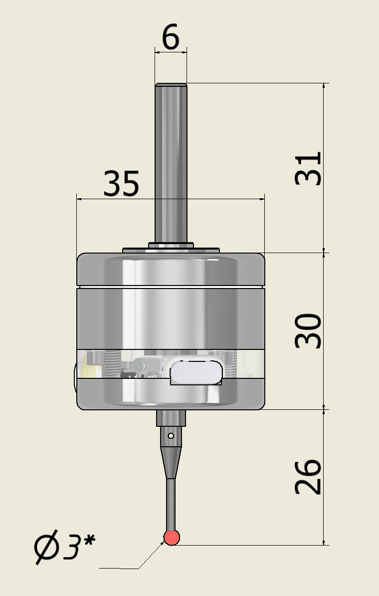
* All dimensions are for reference only. The ball (stylus tip) diameter is approximate and may actually vary within ±0.01 mm, spherical irregularity < 0.001 mm.
Before Getting Started
Please read the information below before starting to use the WL10. Before the first startup, you must:
1. Charge the TP (see the "Connection" section).
2. Find the best location to place the receiver. To do this, follow these steps: Mount the TP in the spindle. Turn on the receiver and the TP. The radio signal has a range of up to 3 meters. The closer the receiver is placed to the working area of the CNC machine, the better the radio communication. Overlapping reflected signals create a complex and unique interference pattern at each workspace. You will need to find a position for the receiver where the radio signal strength indicator on its screen is confidently above -80 dBm. This will eliminate packet loss, duplication, and delays. Keep in mind that metal partitions are opaque to radio signals, so do not place the receiver inside electrical cabinets.
Connection
The WL10 kit consists of 2 devices: the touch probe (TP) and the receiver. For charging at the first startup, connect the receiver to any DC power source from 5 to 24 volts:
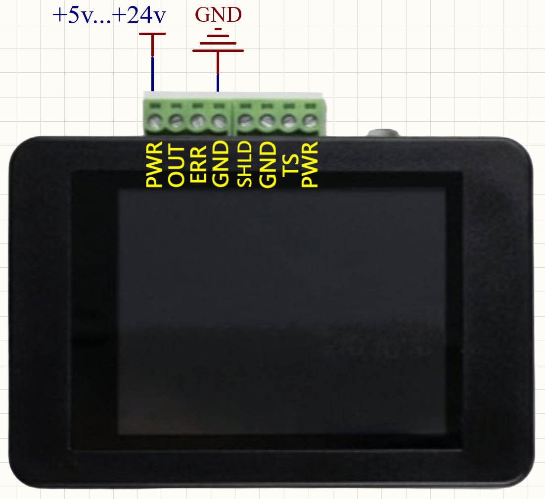
Then connect the receiver and the TP using the included TYPE-C cable. First, turn on the receiver using the button, then the TP. A blue LED inside the TP indicates that the charging process is underway. When the blue LED turns off, the charging process is complete; you can turn off the TP and the receiver and disconnect the TYPE-C cable.
Alternatively, instead of the receiver, you can use any 5-volt DC power source with a TYPE-C connector to charge the TP, such as a mobile phone charger. In this case, simply connect the charger to the TP and turn on the TP with the button.
To find the best location for placing the receiver at the first startup, connect the receiver to any DC power source from 5 to 24 volts and follow step 2 of the "Before Getting Started" section.
Switch Functions and Receiver Connector Pinout
Before connecting the WL10 to the controller, you must configure the switches on the back of the receiver once, according to your CNC system configuration. The switches set the option for connecting a tool setter and the controller connection modes: NC (normally closed), NO (normally open), NPN (switches negative), PNP (switches positive). DIP switches allow enabling pull-up/pull-down resistors.
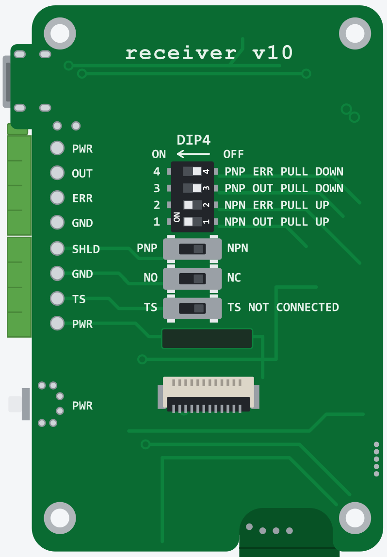
- "TS" Switch — used in combination with the TS input. If you do not use the TS input, this switch must be turned off "TS NOT CONNECTED", which permanently connects the TS input to ground. If you decide to use the TS input, the "TS" switch must be turned on so the receiver begins to monitor the state of this input.
-
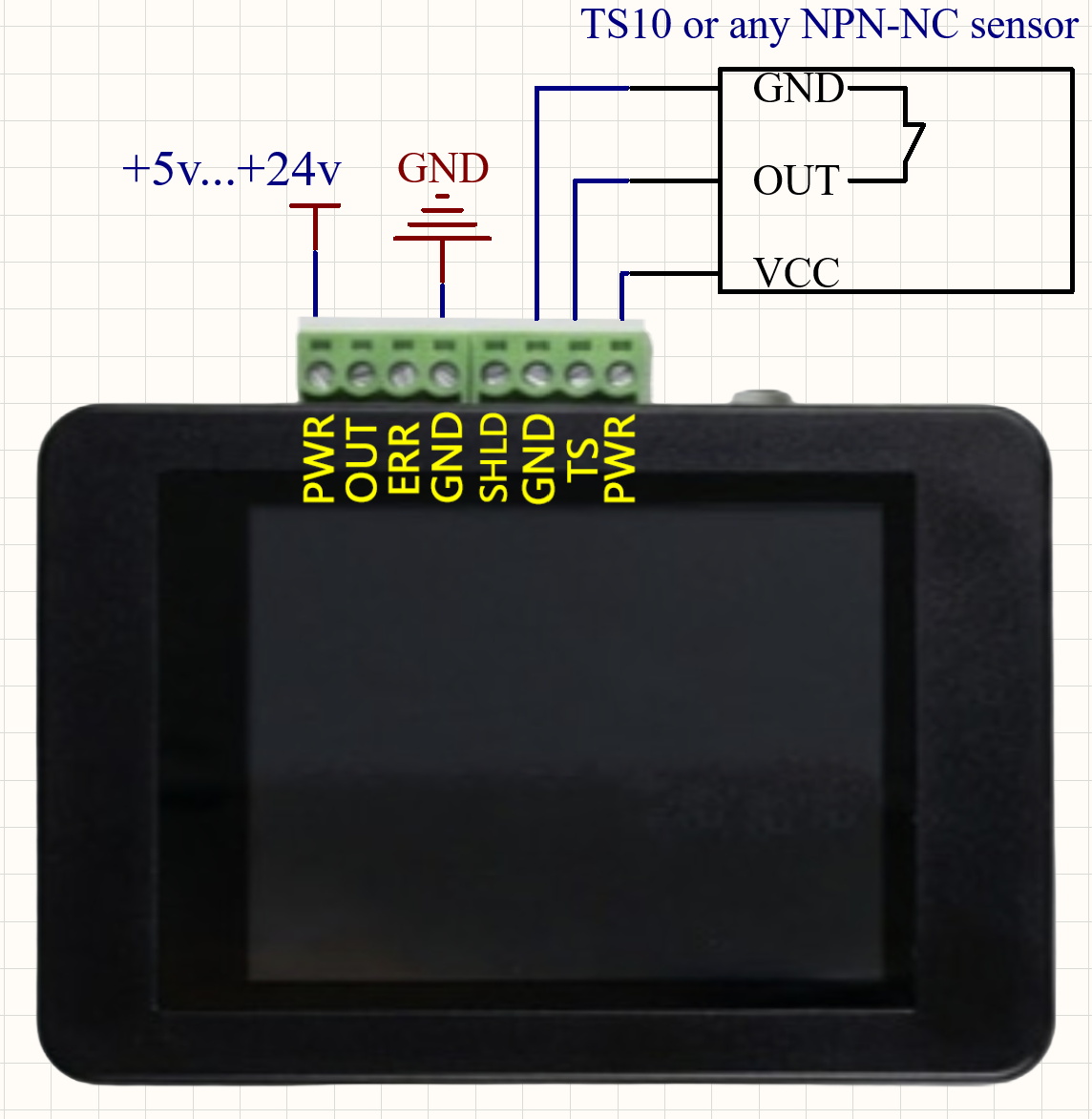
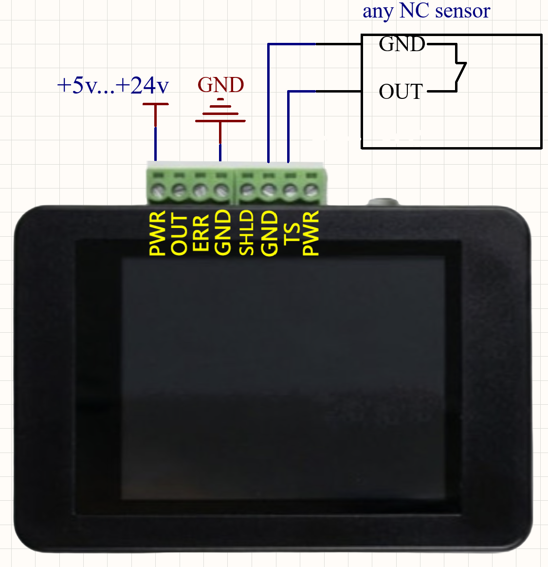
"TS" Input — serves to combine the output of a tool setter (TS10 or another third-party NPN-NC or NC type sensor) with the receiver into one common "OUT" output using a logical "OR" circuit, which allows independent disconnection of either sensor (for example, if the TP goes into sleep mode, the TS10 will remain operational). The TS10 connects to the WL10 as shown in the diagram below and uses the power supply from the WL10 in this case; the TS10 can also use its own power supply.
- "NC-NO" — allows choosing between a normally closed NC (recommended) and a normally open NO output wiring scheme to the controller.
- "NPN-PNP" — allows choosing between an NPN and PNP output wiring scheme to the controller.
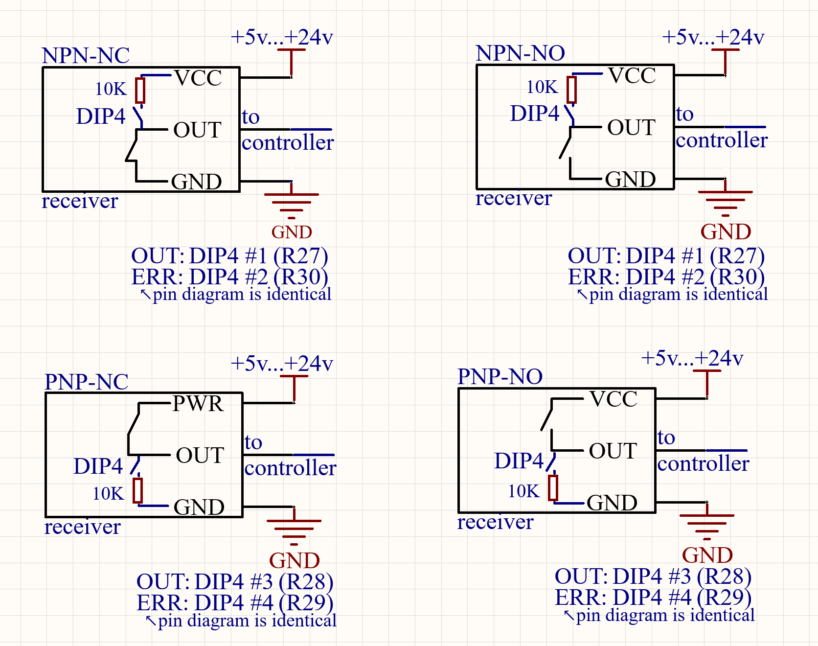
- "DIP4" — connects the corresponding pull-up/pull-down resistor to the OUT and ERR outputs. Used in combination with the "NPN-PNP" switch. In NPN mode, DIP switches #1, #2 are ON, others are OFF. In PNP mode, DIP switches #3, #4 are ON, others are OFF.
- "ERR" — is a logical output that signals excessive delays (more than 1 millisecond). This can occur in the event of weak radio communication (level on the receiver screen below -80 dBm) or severe radio interference. In that case, a duplicate radio packet may need to be sent at the moment of measurement, leading to a delay. It is accompanied by an LED indication on the receiver. It provides the ability to cancel an incorrect measurement if a radio channel response delay occurs at the moment of measurement. A software check of the Error Signal is placed immediately after the probing move G38 (LinuxCNC), G31 (Mach3), before releasing the stylus; if an Error Signal is detected, it is recommended to repeat the measurement.
To work with the ERR signal, 1 free digital input must be allocated on your CNC controller, which can be read at the software level.
The diagrams below show how to use the "NC NO", "NPN PNP", and "DIP4" switches to select one of the 4 wiring schemes for connecting the OUT and ERR outputs to the controller (please note that the controller may have its own power supply voltage limitations).
Screen Interface Navigation
Main Screen:
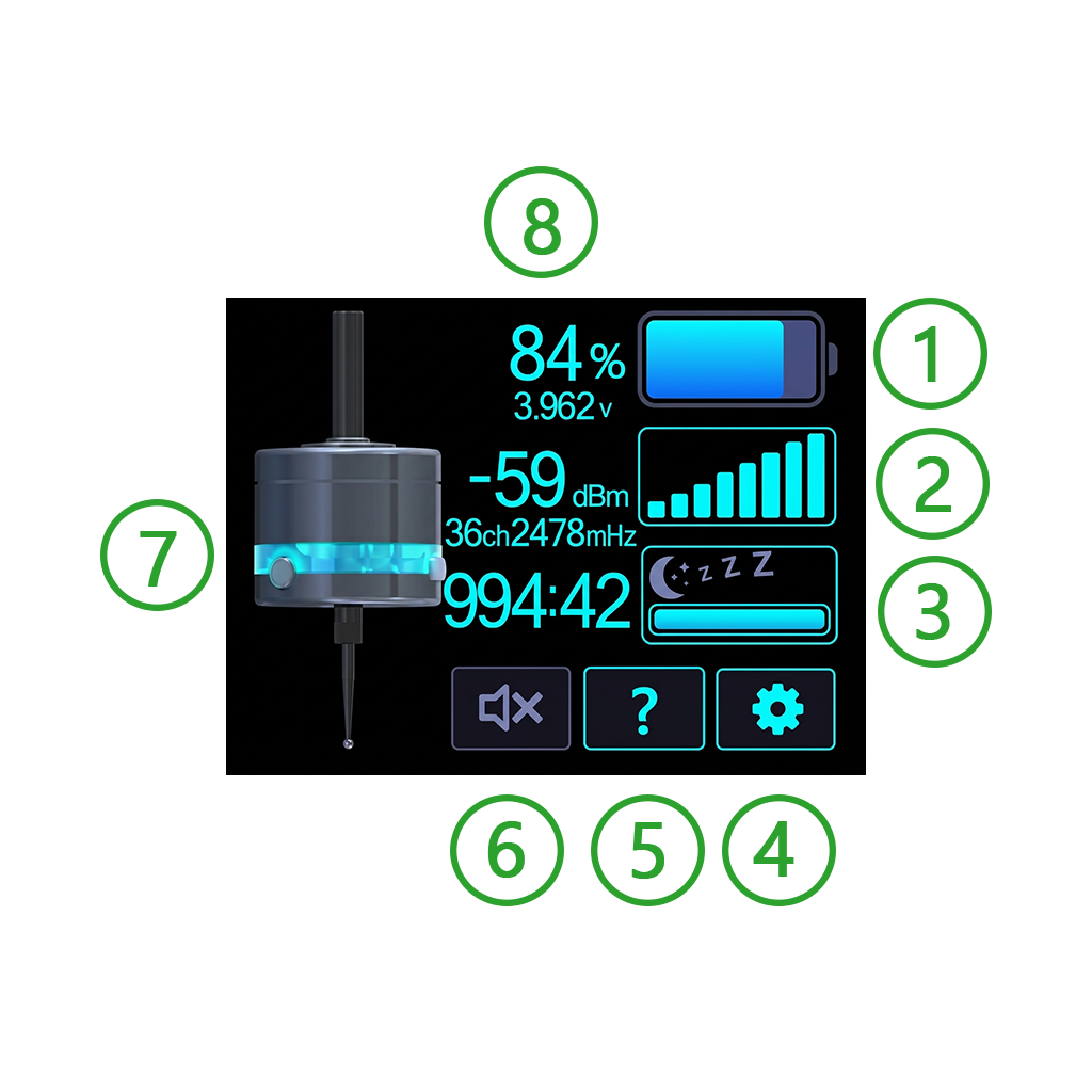
Screen elements 1 through 6 are clickable; the rest are informational.
1 - Battery charge level. Pressing it changes the level of detail in the center of the screen from minimal to full.
2 - Radio signal strength. Navigates to the Radio Setup Screen.
3 - Time until sleep. Navigates to the Sleep Timer Setup Screen.
4 - Navigates to the General Settings Screen.
5 - Navigates to the Help Screen.
6 - Buzzer On/Off.
7 - Stylus status.
8 - TP status.
Radio Setup Screen:
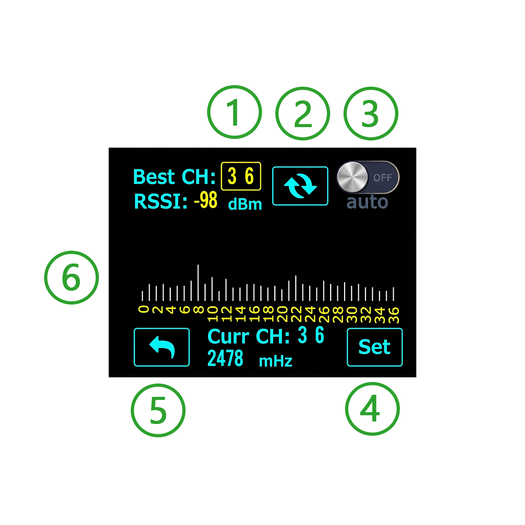
1 - Manual channel number selection from 0 to 36.
2 - Refresh spectrogram.
3 - Toggle automatic channel search mode on and off.
4 - Press and hold until reboot to save changes.
5 - Exit to the Main Screen.
6 - Informational area, spectrogram — noise levels across all channels simultaneously.
Sleep Timer Setup Screen:
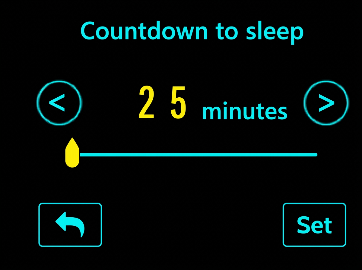
If the TP is not used during this time, it will switch to sleep mode with minimal power consumption. Waking up from sleep mode is done by shaking or rotating it in the spindle at 200 RPM. When the stylus is deflected, the countdown resets to this value and starts over. Set the desired value using the slider or arrows, then press and hold "Set" until reboot to save.
General Settings Screen:
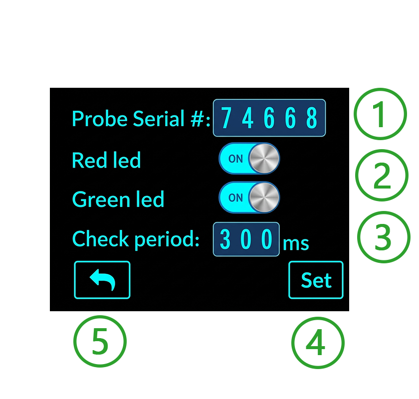
1 - Input field for the TP Serial Number to pair it with the receiver. The 5-digit TP Serial Number is engraved on the TP body. If there is no engraving, the Serial Number corresponds to the order number.
2 - These switches allow disabling the LED indication in the TP to save energy.
3 - Check period: this input field sets the interval between connection check packets between the TP and the receiver. This simulates a normally closed connection for safety purposes.
4 - Press and hold until reboot to save changes.
5 - Exit to the Main Screen.
Help Screen:
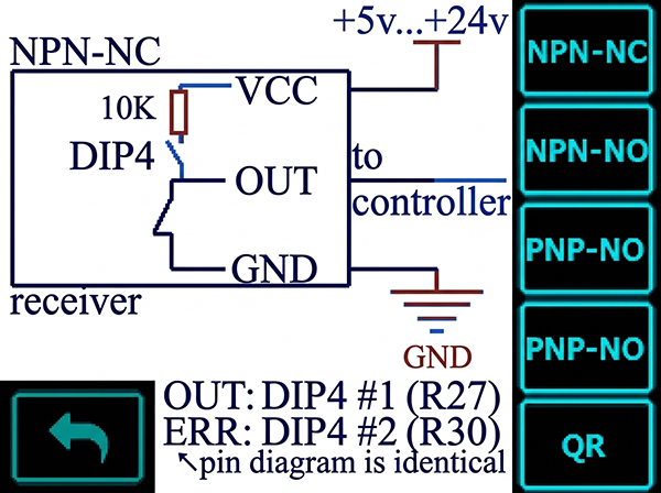
Here are some quick tips.
Pairing the TP with the Receiver
The devices are supplied already paired. This procedure is only needed to pair a receiver and a TP from different kits. Only one TP can be paired to a single receiver.
- 1. Turn off the receiver, the TP, and all WL10 wireless devices located in the same room.
- 2. Turn on the receiver.
- 3. Select the "Settings" section on the screen.
- 4. Enter the serial number of your TP in the corresponding field. Press and hold the "Set" button until it reboots. The 5-digit serial number can be found directly on the TP body, or, if there is no engraving, it corresponds to your order number on the website.
LED Indication
LED Indication in the TP:
- Red LED is lit: stylus is deflected (triggered);
- Green LED (short repeating pulse): normal mode, connected to the receiver; the LED flashes on every fifth check connection packet;
- Blue LED is lit: battery is charging. If the battery is deeply discharged, the blue LED may not turn on immediately until the dynamic control system restores the charge to a safe minimum level. The blue LED will turn off when the charge level reaches 80%.
LEDs are major energy consumers in the TP. They can be disabled if desired in the receiver settings.
LED Indication in the Receiver:
- Blue OUT LED: indicates the logical level of the OUT output;
- Red ERR LED: indicates the logical level of the ERR output.
Wired Operation
The WL10 has the capability to operate via wire in conditions of severe radio interference. The main sources of such radio interference are microwave ovens, welding, and congested Wi-Fi networks. To transmit the sensor trigger signal via the TYPE-C cable, turn off both the probe and the receiver, connect them with the cable, and turn on only the receiver.
Adjustment (Calibration)
Before starting measurements, it is necessary to adjust the TP runout. Mount the TP in the spindle and secure a dial test indicator nearby (see picture below). The indicator must be sensitive to a light force of 0.3-0.5N (most lever-type dial test indicators have this property). Rotate the spindle axis by hand and monitor the amplitude of the stylus ball runout (deviation from the axis of rotation) on the indicator.
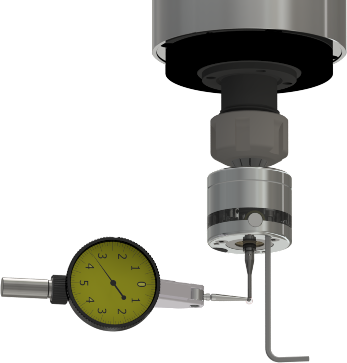
The deviation is eliminated by turning the recessed M2.5 adjustment screws using the included 2 mm hex key. Both tightening and loosening of the screws are used during adjustment. It is recommended to hold the key by the short arm to avoid applying excessive force. It will take several cycles of "spindle rotation — check — adjustment" to achieve the minimum deviation acceptable for a specific measurement.
Usage
The radio channel in the WL10 simulates a normally closed connection between the TP and the receiver. A radio channel loss is identical to a wire break, with the only difference being that the response to a channel break at the OUT or ERR outputs arrives with a delay equal to the Check period (not to be confused with the response delay to stylus deflection < 1 ms). The graph below shows safe speed-acceleration combinations for probing (the green hatched area), at which the machine will stop without breaking the stylus, even in the event of a radio communication failure at the most "unfortunate" moment when the stylus has just touched the part. This takes into account a stylus overtravel of 7 mm and a Check period = 300 ms.
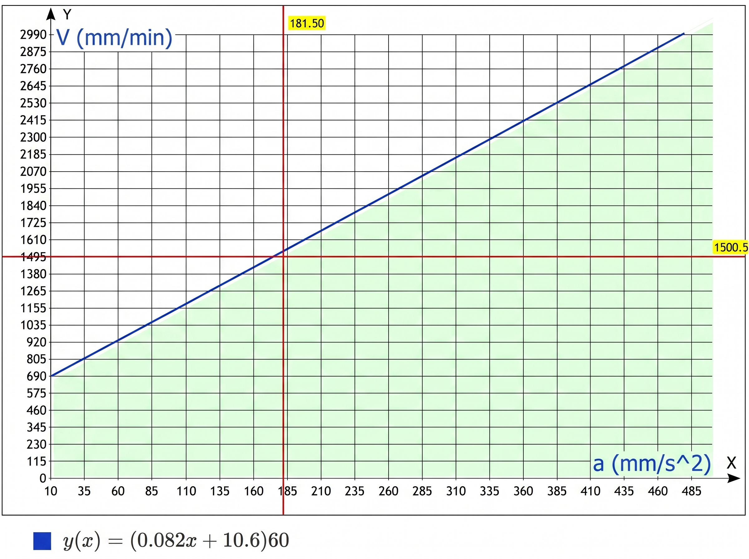
The formula is derived from the initial conditions:
- S = 7 mm — maximum allowable stylus overtravel distance
- t = 0.3 s — maximum delay time for detecting a connection loss, after which deceleration to a full stop begins
- V — probing feedrate in mm/min, Y-axis on the graph
- a — acceleration set in the machine settings, in mm/s², X-axis on the graph
(Formula used for calculations: S = 2*V*t - a*(t²)/2)