
This "User's Guide" refers to the Vers WLR v2. For VersWLR v.1.4 and below the "User's Guide" is located on this link.
Purpose.
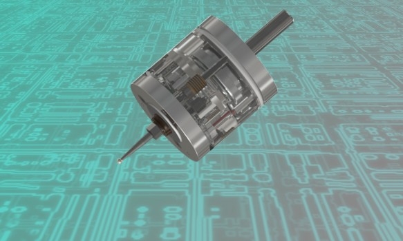
Wireless touch probe VersWLR is designed to determine the exact coordinates of objects mounted on a CNC milling machine. The CNC system generates these coordinates when the VersWLR stylus touches the object and uses them to link the processing program to the workpiece location, to measure lengths, diameters, to search for hole centers, etc. The device can be used with various CNC systems: LinuxCNC, Mach3, embedded systems on industrial machines, etc. The device communicates by air at a frequency of 2.4 GHz with a receiver and then by wire with a CNC system. The transmitter is built into the probe. The receiver is supplied as a separate pcb.
Specifications.
Unidirectional repeatability | < 0.003 mm |
Search directions | ±X, ±Y, -Z |
Permitted deviation stylus in XYZ directions | ±4mm |
Contact force in XY | min 0.5N max 0.8N |
Contact force in Z | 2N |
Delay in the radio channel | ~ 2 ms |
Error detection delay in the radio channel | < 0.33 s |
Power supply of sensor (transmitter) | LIR2477 3.6v |
The possibility of charging | Yes |
Current сonsumption of probe (transmitter) | <0,6mA |
Power supply of receiver | +5v...+24v |
Current сonsumption of receiver (for different Vin) | 21 mA (5v) 14 mA (9v) 12 mA (12v) 8 mA (24v) |
Radius of the radio channel | 6 m |
Radio frequency | 2,4 GHz |
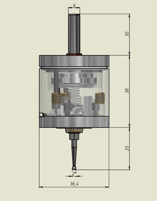
________________
* All sizes are for reference. The diameter of the ball (tip of the stylus) is approximate, in fact it can differ from the specified within ± 0.02 mm, spherical irregularity <0.003 mm.
Features:
-the ability to connect the receiver to power sources in a wide range of +5V ... +24V at the input and at the output,
-the ability to select different schemes of connection to the CNC controller: NPN-PNP, NC-NO,
-hardware implemented ability to integrate with the toolsetter on one common output and work independently,
-the possibility of adjusting the frequency sub-band 2.4 GHz,
-the ability to set sleep modes,
-the ability to control radio reception failures due to a separately derived error signal.
-ultra-low power consumption of the probe (for more details, see below “About radio channel”) when implementing continuous radio communication,
- power supply of the sensor from the LIR2477 3.6v battery with possibility of charging, applied increasing the voltage on the contact group up to + 16v for sure closing of contacts,
-the frequency of recharging with daily use is on average 1-2 times a month, the charging time is 2.5-3 hours, in the process of charging from the receiver, you can continue to use the sensor, charging is also possible from any 5 volt chargers and from the computer USB port.
-when a cable is connected to receiver for charging, the sensor begins to transmit a trip signal on this cable, which can be useful in some cases (for example, with powerful radio interference),
-LED and buzzer indication of events.
About radio channel:
- delay in the radio channel when transmitting a signal from pressing the stylus about 2 milliseconds,
- provides a normally-closed connection of the probe to the receiver (continuous radio communication),
- the reliability of a normally closed loop via a radio channel is provided by a protocol with acknowledgment of reception and duplication of unconfirmed data,
- the delay of the programmed (for triple absence of acknowledgment) response of the receiver to the break of communication over the radio channel is less than 0.33 s, which provides a safe search at a speed, for example, 460mm / min at 100mm / c ^ 2 acceleration (еxcessive movement with a sudden break in the radio at 2.5mm, stopped after another 0.3mm),
- ultra low consumption, power supply of the transceiver from one LIR2477 3.6 volt battery, current consumption in the wake-up mode of the probe (averaged) 0.6mA,
- Sleep mode 1. When not in use, the automatic transition to sleep mode through the user-selected («Time before sleep» switch on the receiver, see below) the time interval. Touching the stylus at 5 seconds removes the probe from the sleep. Current consumption in sleep mode 1 (averaged) - 0.07mA.
- Sleep mode 2. When the receiver is turned off (for example, with the cnc turned off), the probe automatically enters Sleep mode 2. A short automatic wake-up to search for a newly connected receiver will occur every 15 seconds. Current consumption in Sleep mode 2 (averaged) - 0.01mA. Before turning off the receiver, make sure that the stylus is not pressed (the red LED is not lit on the probe), the probe does not go into sleep when the stylus is pressed.
![]() The main reasons for the weakening of the radio signal are: the surrounding Wi-Fi networks, microwave ovens, the proximity of the receiver to large metal objects (placing the receiver closer than 15 cm to them is not recommended). There is a choice for the user from 4 sub-bands of 2.4 GHz radio frequencies to reduce the influence of interference. It is not recommended to install the receiver inside metal cabinets.
The main reasons for the weakening of the radio signal are: the surrounding Wi-Fi networks, microwave ovens, the proximity of the receiver to large metal objects (placing the receiver closer than 15 cm to them is not recommended). There is a choice for the user from 4 sub-bands of 2.4 GHz radio frequencies to reduce the influence of interference. It is not recommended to install the receiver inside metal cabinets.
.
Connection.
![]() The Vers WLR consists of 2 parts: a touch probe and a receiver. To start, you first need to turn on the receiver, then the probe. If you turn off the receiver, the turned-on probe is always in Sleep mode 2, a short awakening to search for the receiver and restore communication occurs automatically every 15 seconds.
The Vers WLR consists of 2 parts: a touch probe and a receiver. To start, you first need to turn on the receiver, then the probe. If you turn off the receiver, the turned-on probe is always in Sleep mode 2, a short awakening to search for the receiver and restore communication occurs automatically every 15 seconds.
![]() To charge the battery, you need to turn off the receiver, turn on the probe, connect them with the USB cable from the kit, turn on the receiver. The probe can be used for measurements. Also (since v.2), instead of the receiver, you can use any 5 volt DC source with a USB port for charging, as well as a computer USB port, in this case there is no connection with the receiver and the probe is not available for use during charging.
To charge the battery, you need to turn off the receiver, turn on the probe, connect them with the USB cable from the kit, turn on the receiver. The probe can be used for measurements. Also (since v.2), instead of the receiver, you can use any 5 volt DC source with a USB port for charging, as well as a computer USB port, in this case there is no connection with the receiver and the probe is not available for use during charging.
Functions of switches and pinout of the receiver connector.
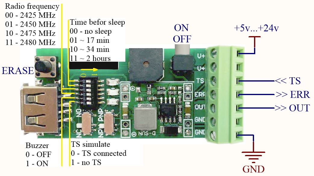
«Time before sleep» specifies the interval of inactivity of the probe, through which the probe will automatically enter sleep mode. Exit from that sleep mode - by hold down the stylus 5 seconds. There is an important difference in the receiver's operation, depending on whether "Time to Sleep" is set or off (in the state of the switches 00). If the "Time to Sleep" is not set, turning off the probe or breaking the radio has the same effect as pressing the stylus - the output signal appears on the OUT of the receiver. If the "Time to Sleep" is set, turning off the probe, or going it into sleep, or breaking the radio does not affect the OUT output, but initiates the ERR output. This allows you to continue to use the second connected TS sensor. When "Time to Sleep" is set, it is recommended either to press the stylus for waking 5 seconds or to test the ERR signal before each measurement and 5 seconds to press the stylus only if there is an ERR signal.
«Radio frequency» sets the frequency subband of the 2.4GHz channel. The best sub-band is the one in which the blue LED is less frequently lit (blue LED is a visual indication of the ERROR signal).
Output "ERR" -The ERROR signal is connected as npn-nc only, it is a detector of excessive (more than 2 milliseconds) delays in the radio channel. Provides the ability to cancel an incorrect measurement in the event of a delay in the response of the radio channel at the time of touch. Program check an ERROR signal is placed immediately after searching for G38 (linuxcnc), G31 (mach3), in case of an ERROR signal the measurement should be ignored and repeated anew. Alternatively, you can not use ERR, then for complete confidence in the measurement, measure one place twice and take it if both measurements coincide with the required accuracy. The main cause of the error signal is the surrounding WiFi networks. To minimize their influence, it is possible to switch between the 4 alternative sub-bands of 2.4 GHz radio frequency switches. The best sub-band is the one in which the blue LED is less frequently lit (blue LED is a visual indication of the ERROR signal). Also, the ERR is used to determine if it is necessary to take out the probe from Sleep Mode 1. The software must check the Error Signal before searching for G38 (linuxcnc), G31 (mach3), if a ERR Error is detected, 5 second pressing on the stylus is performed to wake up.
To work with the Err signal, it is necessary that your cnc controller has 1 free input pin.
Err out should be considered as a separate npn-nc sensor that connects to this input pin.
For LinuxCNC users:
The Optional Interpreter feature needs to be turned-on. http://linuxcnc.org/docs/2.7/html/remap/remap.html#_optional_interpreter_features_ini_file_configuration
[RS274NGC]
FEATURES = 30
In the configuration .hal file, this input is assigned a digital pin:
net signal-name motion.digital-in-00 <= parport.0.pin10-in
The state of the digital input is read in the right place of the g-code program using the command M66, http://linuxcnc.org/docs/html/gcode/m-code.html#mcode:m66
M66 P0 L0
The current value of the input is stored in parameter #5399", For check it
(DEBUG, #5399)
o100 if [#5399 EQ 1]
"Buzzer" activates the sound signal by pressing the stylus.
«NC NO» selects between a normally closed NC (recommended) and a normally open NO connection circuit for output pin.
«NPN PNP» selects between npn and pnp the connection circuit for output pin.
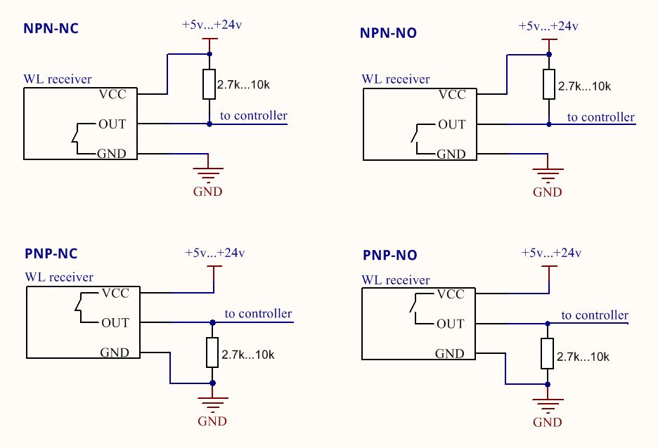
Switches «NC NO» and «NPN PNP» selects one of the 4 circuits of the receiver connection to controller (note, the controller may have its own supply voltage limits).
The pull-up resistor shown in the diagrams below is sometimes already present in the controller, in which case it does not need to be installed. For connection details, refer to the user manual for your controller.
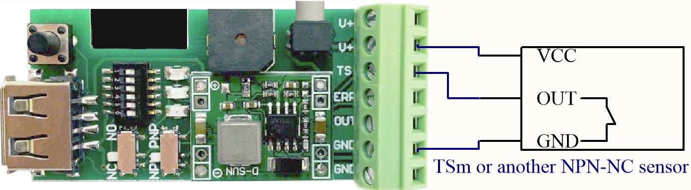
Input "TS" is used to connect the tool setter Vers TSm or WTSm (or other third-party NPN-NC or NC type sensors) to the VersWLR receiver to one common "OUT" output in the OR logic, which allows any of the sensors to be switched off independently (for example, if WLR "gone into a sleep", TSm will remain in working order). The TSm connects to the WLR as shown in the diagram below and in this case uses the WLR power supply. TSm can also use its own power supply.
LED indication on probe
- green LED 1 short pulse every 2.5 seconds: the probe is on and ready to work;
- the red LED is on: the stylus is pressed;
- green LED 5 short pulses in a row when the probe is turned on: the battery will soon end, but you can continue to work for several more days after the appearance of such signal for the first time; in such mode, spontaneous "trips" of the probe up to the constantly burning red LED gradually begin to appear, which means that it is time to change the battery, the battery voltage without load should not be below 2.8 volts;
- the green LED is constantly lit or switches 2 times per second: the link with the receiver is broken, it is necessary to restart (off-on) the receiver, and then the probe.
- the blue LED is on: the battery is charging, with a strong battery discharge the blue LED may not turn on immediately while the dynamic control system restores the charge to a safe minimum level.
Adjustment.
It is necessary to adjust the probe before starting the measurement. The probe is installed in the spindle, a check indicator is placed near to it (Fig. 1)
The indicator should be sensitive to a weak effect of 0.3-0.5N (for example, most lever indicators have this property).
The axis of the spindle is rotated by hand and the amplitude of the deflection of the stylus ball from the axis of rotation is controlled by the indicator.
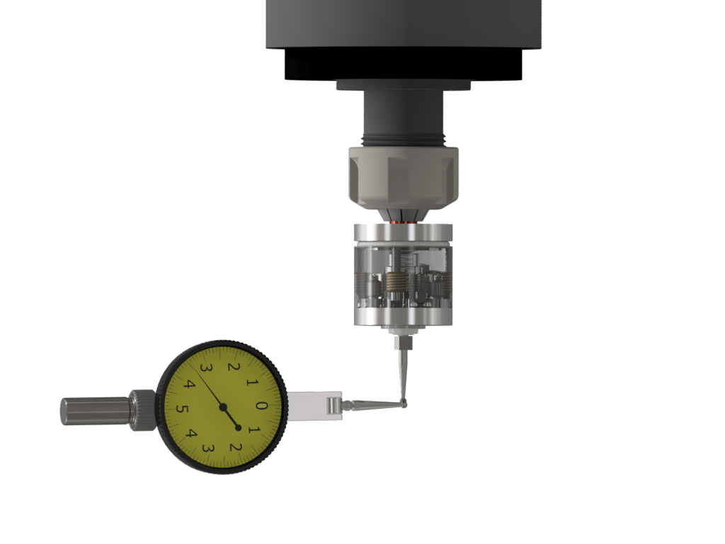
Fig.1
The deviation is eliminated by turning the adjusting screws M2.5 (the screws are recessed into the holes indicated by the green arrows in Fig. 2) with a 2mm hex key from the kit. When adjusting, both tightening and loosening of the screws are used.
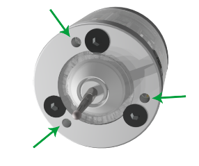
Fig.2
It is recommended to hold for a short lever of the key , so as not to develop excessive force (Fig. 3). It will be necessary to perform several cycles of spindle axis rotation--control-- adjustment in order to achieve a minimum deviation acceptable for a particular measurement.
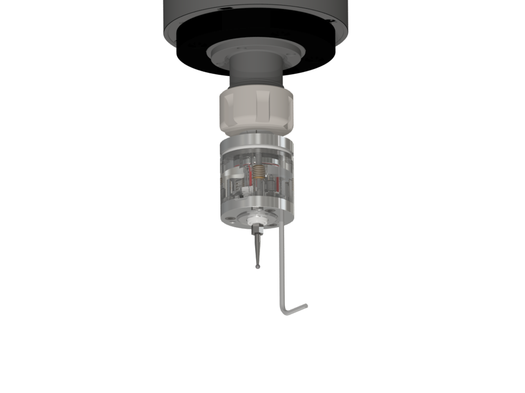
Fig.3
Using.
The radio channel in the Vers WLR supports continuous radio communication, thereby simulating a normally-closed loop of transmitter-receiver interconnect. A broken radio link is identical to a broken wire, with the only difference being that on the receiver side, which is directly connected to the machine, the response to a broken link, a signal at the OUT or ERR outputs, comes with a delay of 0 to 0.33 seconds (do not confuse with a delayed response to pressing stylus ~ 2ms). This is a deliberate compromise to save battery in the Vers WLR. The graph below shows the speed-acceleration combinations that are safe for searching (area with green hatching), at which the machine will stop exactly in time without breaking the stylus, even in case of an emergency radio link failure at the most “unsuccessful” moment when the stylus touches the part.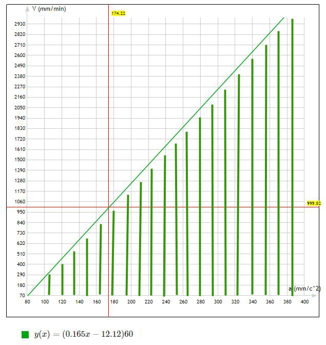
Formula is derived from initial conditions:
S = 4 mm permitted deviation stylus
t = 0.33c maximum delay time for detecting a communication break and then let it be the same (for example) to slow down and stop completely.
V - search speed in mm/min, Y axis on the graph
a - acceleration specified in the machine settings, in mm/c ^ 2, X axis on the graph
(Formula used: S = -V * t + a * (t ^ 2) / 2 is the distance to move from initial velocity V to zero with acceleration a in time t)
There is software ProbeScreen in free access for convenient work with probe in the LinuxCNC(ver.2.6 , 2.7)
Probe Wizard - in the Mach3 system.