
This "User's Guide" refers to Vers WTSm v.1.4 models and below.
Purpose.
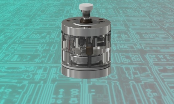
The Vers WTSm sensor is used to determine the exact coordinates of the tool installed on a CNC milling machine by contact method. The CNC system generates these coordinates when the tool touchs the Vers WTSR measurement platform and uses them to calculate the height and diameter of the tool. The device can be used with various CNC systems: LinuxCNC, Mach3, embedded systems on industrial machines, etc. The device communicates by air at a frequency of 2.4 GHz with a receiver and then by wire with a CNC system. The transmitter is built into the tool setter. The receiver is supplied as a separate pcb.
Specifications.
Unidirectional repeatability | < 0.003 mm |
Search directions | ±X, ±Y, -Z |
Permitted deviation of the measuring pad in XYZ directions | ±4mm |
Contact force | min 0.5N max 2N |
Diameter and overall height | D=32.4mm, H=47mm |
Diameter and height of the ceramic pad | D=10mm, h=2.5mm |
Delay in the radio channel | ~ 2 ms |
Error detection delay in the radio channel | < 0.33 s |
Power supply of sensor (transmitter) | LIR2477 3.6v |
The possibility of charging | Yes |
Current сonsumption of sensor (transmitter) | <0,6mA |
Power supply of receiver | +5v...+24v |
Current сonsumption of receiver (for different Vin) | 21 mA (5v) 14 mA (9v) 12 mA (12v) 8 mA (24v) |
Radius of the radio channel | 6 m |
Radio frequency | 2,4 GHz |
Dust protection | Yes |
Adjustability | Yes |
Features:
-the ability to connect the receiver to power sources in a wide range of +5V ... +24V at the input and at the output,
-the ability to select different schemes of connection to the CNC controller: NPN-PNP, NC-NO,
-hardware implemented ability to integrate with a wired NPN-NC or NC sensor (in particular, with a touch probe Vers PR) on one common output and work independently,
-the possibility of adjusting the frequency sub-band 2.4 GHz,
-the ability to set sleep modes,
-the ability to control radio reception failures due to a separately derived error signal.
-ultra-low power consumption of the sensor (for more details, see below “About radio channel”) when implementing continuous radio communication,
- power supply of the sensor from the LIR2477 3.6v battery with possibility of charging, applied increasing the voltage on the contact group up to + 16v for sure closing of contacts,
-the frequency of recharging with daily use is on average 1 time per month, the charging time is 2.5-3 hours, you can continue to use the sensor during charging.
-when a cable is connected for recharging, the sensor begins to transmit a trip signal on this cable, which can be useful in some cases (for example, with powerful radio interference),
-LED and buzzer indication of events.
About radio channel:
- delay in the radio channel when transmitting a signal from pressing the pad about 2 milliseconds,
- provides a normally-closed connection of the sensor to the receiver (continuous radio communication),
- the reliability of a normally closed loop via a radio channel is provided by a protocol with acknowledgment of reception and duplication of unconfirmed data,
- the delay of the programmed (for triple absence of acknowledgment) response of the receiver to the break of communication over the radio channel is less than 0.33 s, which provides a safe search at a speed, for example, 460mm / min at 100mm / c ^ 2 acceleration (еxcessive movement with a sudden break in the radio at 2.5mm, stopped after another 0.3mm),
- ultra low consumption, power supply of the transceiver from one LIR2477 3.6 volt battery, current consumption in the wake-up mode of the sensor (averaged) 0.6mA,
- Sleep mode 1. When not in use, the automatic transition to sleep mode through the user-selected («Time before sleep» switch on the receiver, see below) the time interval. Touching the pad at 5 seconds removes the sensor from the sleep. Current consumption in sleep mode 1 (averaged) - 0.07mA.
- Sleep mode 2. When the receiver is turned off (for example, with the cnc turned off), the sensor automatically enters Sleep mode 2. A short automatic wake-up to search for a newly connected receiver will occur every 15 seconds. Current consumption in Sleep mode 2 (averaged) - 0.01mA. Before turning off the receiver, make sure that the pad is not pressed (the red LED is not lit on the sensor), the sensor does not go into sleep when the pad is pressed.
![]() The main reasons for the weakening of the radio signal are the surrounding Wi-Fi networks and the proximity of the receiver to large metal objects (placing the receiver closer than 20 cm to them is not recommended). For coexistence with Wi-Fi networks, there is a choice for the user from 4 sub-bands of 2.4 GHz radio frequencies. It is not recommended to install the receiver inside metal cabinets.
The main reasons for the weakening of the radio signal are the surrounding Wi-Fi networks and the proximity of the receiver to large metal objects (placing the receiver closer than 20 cm to them is not recommended). For coexistence with Wi-Fi networks, there is a choice for the user from 4 sub-bands of 2.4 GHz radio frequencies. It is not recommended to install the receiver inside metal cabinets.
.
Installation.
![]() Placement Vesr WTSm is recommended to be chosen so that the entire surface of the ceramic platform of the device is in the working area of the machine, with an indent from the boundaries = the maximum diameter of the tool being measured + 2mm.
Placement Vesr WTSm is recommended to be chosen so that the entire surface of the ceramic platform of the device is in the working area of the machine, with an indent from the boundaries = the maximum diameter of the tool being measured + 2mm.
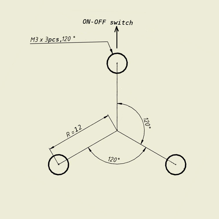
The device is fixed to the machine body with three M3 screws. Three threaded holes are prefabricated in the machine body:
Adjustment.
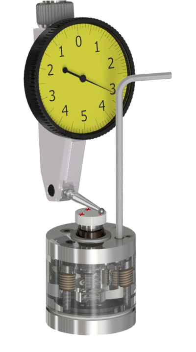
Before starting the measurement, it is necessary to adjust the device. As a result of the adjustment, the surface of the measuring platform should become parallel to the XY plane.
![]() The indicator should be sensitive to a weak effect of 0.3-0.5N (for example, most lever indicators have this property).
The indicator should be sensitive to a weak effect of 0.3-0.5N (for example, most lever indicators have this property).
For adjustment, three points are selected at the measuring pad (shown with red crosses) approximately at the edge of the site in the direction of the adjustment holes. The indicator is set in the spindle (you will need to moving the spindle in XY coordinates), the stylus of the indicator is located to measure the deviations in height. The results of the indicator must have to the same values in these three selected points. For adjustment, a 2mm hex key is used from the kit, both screwing in and loosening of the adjustment screws located inside the holes, closed with elastic bands. The key is recommended to hold for a short lever, so as not to develop excessive force when screwing.
Connection.
![]() The Vers WTSm consists of 2 parts: a sensor and a receiver board (pictured below). To start, you first need to turn ON the receiver. When the receiver is turned OFF, the sensor is always in Sleep mode 2, the awakening takes place automatically within 15 seconds after switching ON the receiver.
The Vers WTSm consists of 2 parts: a sensor and a receiver board (pictured below). To start, you first need to turn ON the receiver. When the receiver is turned OFF, the sensor is always in Sleep mode 2, the awakening takes place automatically within 15 seconds after switching ON the receiver.
Pinout of the connector and function of the receiver switches.


«Time before sleep» specifies the interval of inactivity of the sensor, through which the sensor will automatically enter sleep mode. Exit from that sleep mode - by hold down the pad 5 seconds. There is an important difference in the receiver's operation, depending on whether "Time to Sleep" is set or off (in the state of the switches 00). If the "Time to Sleep" is not set, turning off the sensor or breaking the radio has the same effect as pressing the pad - the output signal appears on the OUT of the receiver. If the "Time to Sleep" is set, turning off the sensor, or going it into sleep, or breaking the radio does not affect the OUT output, but initiates the ERR output. This allows you to continue to use the second connected sensor. When "Time to Sleep" is set, it is recommended either to press the pad for waking 5 seconds or to test the ERR signal before each measurement and 5 seconds to press the pad only if there is an ERR signal.
«Radio frequency» sets the frequency subband of the 2.4GHz channel. The best sub-band is the one in which the blue LED is less frequently lit (blue LED is a visual indication of the ERROR signal).
Output "ERR" -The ERROR signal is connected as npn-nc only, it is a detector of excessive (more than 2 milliseconds) delays in the radio channel. Provides the ability to cancel an incorrect measurement in the event of a delay in the response of the radio channel. Program check an ERROR signal is placed immediately after searching for G38 (linuxcnc), G31 (mach3), in case of an ERROR signal the measurement should be ignored and repeated anew. The main cause of the error signal is the surrounding WiFi networks. To minimize their influence, it is possible to switch between the 4 alternative sub-bands of 2.4 GHz radio frequency switches. The best sub-band is the one in which the blue LED is less frequently lit (blue LED is a visual indication of the ERROR signal). Also, the ERR is used to determine if it is necessary to take out the sensor from Sleep Mode 1. The software must check the Error Signal before searching for G38 (linuxcnc), G31 (mach3), if a ERR Error is detected, 5 second pressing on the pad is performed to wake up.
"Buzzer" activates the sound signal by pressing the pad.
«NC NO» selects between a normally closed (recommended) and a normally open connection circuit.
«NPN PNP» selects between npn and pnp the connection scheme.
Input "TS" is used to connect the touch probe (Vers PR, Vers WL or other NPN-NC or NC type sensors) to the Vers WTSR receiver to one common "OUT" output in the OR logic, which allows any of the sensors to be switched off independently (for example, if WTSm "gone into a sleep", second sensor will remain in working order). Connect to the WTSm as shown in the diagram below and in this case use the WTSm power supply. Second sensor can also uses its own power supply.


The switch on the sensor is used to turn the device ON and OFF

Location of microUSB jack for connecting the supplied charging cable

LED indication
- green LED 1 short pulse every 2.5 seconds: the sensor is on and ready to work;
- the red LED is on: the pad is pressed;
- green LED 5 short pulses in a row when the sensor is turned on: the battery will soon end, but you can continue to work for several more days after the appearance of such signal for the first time;
- the green LED is constantly lit or switches 2 times per second: the link with the receiver is broken, it is necessary to restart (off-on) the receiver, and then the sensor.
- the blue LED is on: the battery is charging, with a strong battery discharge the blue LED may not turn on immediately while the dynamic control system restores the charge to a safe minimum level.
Switches «NC NO» and «NPN PNP» selects one of the 4 circuits of the receiver connection to controller (note, the controller may have its own supply voltage limits)

Using.
There is software ProbeScreen and Auto Tool Measurement in free access for convenient work with probe in the LinuxCNC(ver.2.6 and higher),
Probe Wizard - in the Mach3 system.