
This User's Guide applies to Vers WLR v7 models. For earlier versions, the User's Guide can be found at this link.
Purpose
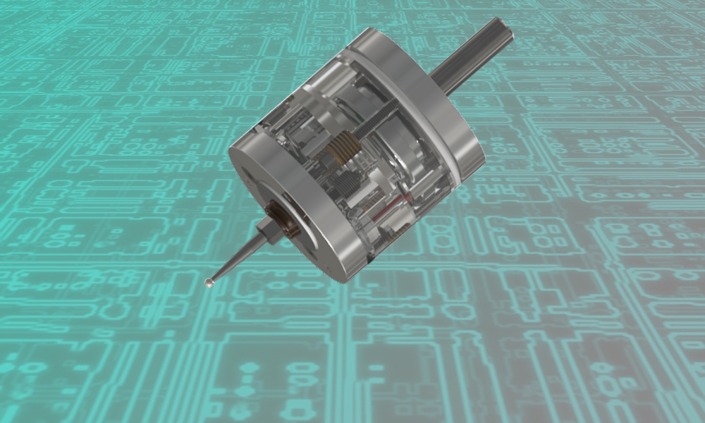
The Vers WLR wireless touch probe is designed to determine the exact coordinates of objects mounted on a CNC milling machine. The CNC system generates these coordinates when probe stylus touches the object and uses them to link the machining program to the location of the workpiece, to measure lengths, diameters, find hole centers, etc. The device can be used with various CNC systems: LinuxCNC, Mach3, embedded systems industrial machines, etc. The probe communicates with the receiver at 2.4 GHz radio frequency, then the receiver is wired to the CNC system. The transmitter is built into the probe. The receiver is included in the kit.
What's new in v7
1. Tungsten carbide on pin-ball contacts.
2. Unidirectional repeatability < 0.002 mm.
3. Permitted deviation stylus in XY ±7mm, Z -4mm.
4. Splash protection for probe.
5. New box for receiver.
6. Firmware and electronics update:
- automatic search for the best of 16 2.4 GHz sub-bands when the receiver is turned on,
- radio signal level indication every time you press the stylus,
- battery level indication,
- a vibration sensor has been added to the probe that allows to wake up from deep sleep by shaking or rotating in the spindle from 200 rpm,
- the delay is reduced to 1.5 milliseconds,
- receiver outputs are protected against short circuits to power or GND,
All the useful functionality of previous versions has been retained, such as the ability to connect a toolsetter, the ability to work by wire, the choice of sleep modes, etc.
Specifications
Unidirectional repeatability | < 0.002 mm |
Search directions | ±X, ±Y, -Z |
Permitted deviation stylus in XY directions | ±7mm |
Permitted deviation stylus in Z directions | 4mm |
Contact force in XY | min 0.5N max 0.8N |
Contact force in Z | 2N |
Delay in the radio channel | 1,5 ms |
Power supply of probe (transmitter) | LIR2477 3.6v |
The possibility of charging | Yes |
Current сonsumption of probe | <0,6mA |
Current сonsumption in sleep mode | <0,06mA |
Power supply of receiver | +5v...+24v |
Current сonsumption of receiver (for different Vin) | 21 mA (5v) 14 mA (9v) 12 mA (12v) 8 mA (24v) |
Radius of the radio channel | 6 m |
Radio frequency | 2,4 GHz |
________________
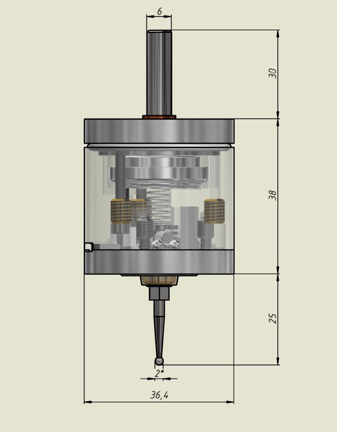
* All sizes are for reference. The diameter of the ball (tip of the stylus) is approximate, in fact it can differ from the specified within ± 0.02 mm, spherical irregularity <0.002 mm.
Features:
- the ability to connect the receiver to power sources in a wide range of +5V ... +24V at the input and at the output,
- the ability to select different schemes of connection to the CNC controller: NPN-PNP, NC-NO,
- hardware implemented ability to integrate with npn-nc toolsetter on one common output and work independently,
- automatic selection of the most unloaded frequency sub-band 2.4 GHz,
- the ability to set sleep modes,
- the ability to correct signal delays thanks to a separately outputted error signal.
- ultra-low current consumption by the probe, 0.6 ma when realizing continuous radio communication, 0.06 ma in sleep mode, 0 ma when the power button is off,
- power supply of the sensor from the LIR2477 3.6v battery with possibility of charging, applied increasing the voltage on the contact group up to + 16v for sure closing of contacts,
- the frequency of recharging with daily use is on average 1-2 times a month, the charging time is 2 hours. You can continue to use the sensor when charging from the receiver, charging is also possible from any 5 volt chargers and from the computer USB port.
- when probe is connected to receiver with usb cable, probe trigger signal will be transmitted through this cable, which can be useful in some cases (for example, with powerful radio interference),
- LED and buzzer indication of stylus pressing, radio signal level, battery charge level, error signal.
About radio channel:
- the delay in the radio channel is 0.75 milliseconds, in the entire chain from the ball contacts of the sensor to the output signal of the receiver is 1.5 milliseconds,
- provides a normally-closed connection of the probe to the receiver (continuous radio communication),
- the reliability of a normally closed loop via a radio channel is provided by a protocol with acknowledgment of reception and duplication of unconfirmed data,
- the delay of the programmed (for triple absence of acknowledgment) response of the receiver to the break of communication over the radio channel is less than 0.3 s, which provides a safe search at speed up to 1000 mm/min,
- ultra low consumption, power supply of the transceiver from one LIR2477 3.6 volt battery, current consumption in the wake-up mode of the probe (averaged) 0.6mA,
- Sleep mode 1. When the probe is not in use, automatic transition to Sleep mode after a user-selected time interval (switch "Time to sleep" on the receiver, see below). Shaking or rotating in the spindle from 200 rpm wakes up the probe. Another way to enter Sleep Mode 1 is to hold pressed the stylus for 10 seconds. Current consumption in Sleep mode 1 - 0.06 mA. Sleep mode 2. When the receiver is turned off (for example, together with turning off the machine), the probe automatically switches to Sleep mode 2. A short automatic wakeup to search for a newly connected receiver will occur every 15 seconds. If before turning off the receiver the probe was already in Sleep mode 1, then it will remain in it. Current consumption in Sleep mode 2 - 0.07 mA. Before turning off the receiver, make sure that the stylus is not pressed (the red LEDs on the probe is not lit), the probe will not go to sleep when the stylus is pressed.
Connection
![]() The Vers WLR consists of 2 parts: a touch probe and a receiver. To start, you first need to turn on the receiver, then the probe.
The Vers WLR consists of 2 parts: a touch probe and a receiver. To start, you first need to turn on the receiver, then the probe.
![]() To charge the battery, turn OFF the probe and receiver, connect them with the supplied USB cable, turn ON the probe, than receiver. Also , instead of the receiver, you can use any 5 volt DC source for charging.
To charge the battery, turn OFF the probe and receiver, connect them with the supplied USB cable, turn ON the probe, than receiver. Also , instead of the receiver, you can use any 5 volt DC source for charging.
![]() To transmit the probe trigger signal via USB cable, turn OFF the probe and receiver, connect them with the supplied USB cable, turn ON receiver only.
To transmit the probe trigger signal via USB cable, turn OFF the probe and receiver, connect them with the supplied USB cable, turn ON receiver only.
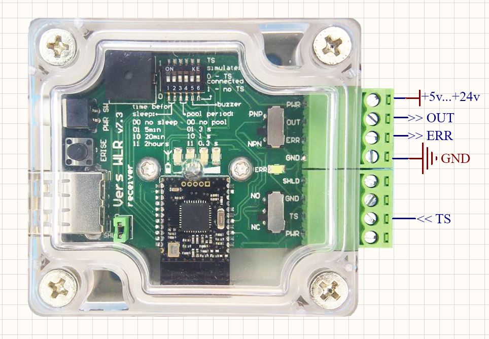
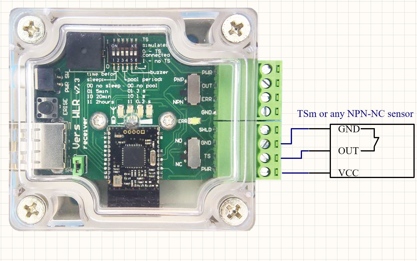
Functions of switches and pinout of the receiver connector.
«time before sleep» defines the period of probe inactivity after which the probe will automatically enter sleep mode. Exiting this sleep mode is by shaking the probe or rotating the spindle at 200 rpm, but not more than 1500 rpm.
«pool period» defines the time interval between sending short handshaking packets. This approach simulates a normally closed connection.
"TS simulate" If you are not using the TS input, this switch must be turned ON. The switch permanently connects the TS input to GND. If you decide to use the TS input, then the "TS simulate" switch must be turned OFF.
"buzzer" activates the sound signal by pressing the stylus.
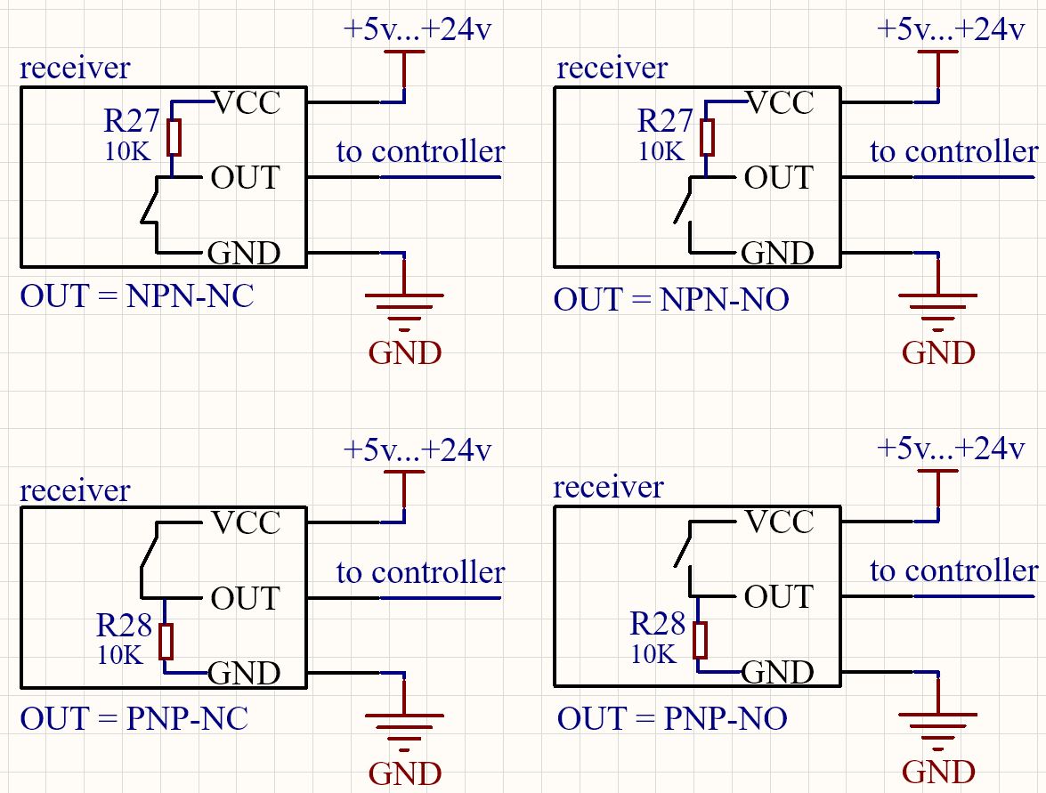
«NC NO» selects between a normally closed NC (recommended) and a normally open NO connection circuit for output pin.
«NPN PNP» selects between npn and pnp the connection circuit for output pin.
Switches «NC NO» and «NPN PNP» selects one of the 4 circuits of the receiver connection to controller (note, the controller may have its own supply voltage limits).
Pull-up (pull-down) resistors are already soldered at the outputs of the receiver, see the diagrams below.
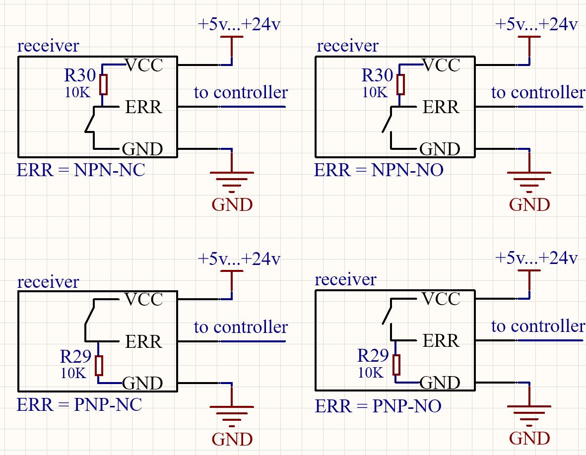
Output "OUT" is the main logical output, which signals that the probe is triggered. This output must be physically connected by wire to the corresponding input in the CNC controller.
Output "ERR" is a logic output that signals excessive (more than 1.7 milliseconds) delays. Accompanied by inversion of the logical level at the ERR pin and indication by a red LED in the receiver. The signal lasts as long as the stylus is pressed and returns to normal when the stylus is released. Provides the ability to cancel an incorrect measurement in case of of excessive radio delays. A delay can occur if the previous sending of a short communication acknowledgement packet has not been completed at the time the stylus is pressed, the delay can be up to 12 ms. The probability of such an event depends on the packet confirmation period specified by the user (pool period): 0.2s - 8%, 0.3s - 3% (recommended), 1s - 1%. A software check of the ERR signal is performed immediately after the g-code search command (for example, this is G38 in linuxcnc, G31 in mach3), before releasing the stylus. If an ERR signal is detected, it is recommended to repeat the measurement. Alternatively, you can not use ERR, then, to be completely sure of the measurement, measure the same location twice and accept if both measurements coincide with the required accuracy. Additionally, if you are measuring at a speed of <10 mm/min, the error from the maximum possible delay will be <0.002 mm, which may be sufficient in some cases. ERR is also used to determine whether the probe should be awakened from sleep mode. To wake up in manual mode - shaking, in automatic mode - a software check of the ERR signal is performed before searching for G38 (linuxcnc), G31 (max3), if an ERR signal is detected it is necessary to turn the probe in the spindle at a speed of 200 - 1500 rpm.
To work with the ERR signal, your CNC controller must have 1 free digital input that can be read at the program level.
Input "TS" is used to connect the tool setter Vers TSm or WTSm (or other third-party NPN-NC or NC type sensors) to the VersWLR receiver to one common "OUT" output in the OR logic, which allows any of the sensors to be switched off independently (for example, if WLR "gone into a sleep", TSm will remain in working order). The TSm connects to the WLR as shown in the diagram below and in this case uses the WLR power supply. TSm can also use its own power supply.
"SERV" button - when the receiver is switched on and that button is pressed simultaneously, one of two service procedures is performed:
1. "Binding probe to receiver" if the probe is connected to the receiver with a USB cable.
2. "Storing TS status" if the probe is not connected to the receiver with a USB cable.
Binding probe to receiver
The devices are shipped with the binding procedure already completed. This procedure is only needed to bind the receiver and probe from different kits.
1. Turn off the receiver, probe, and all Vers wireless devices in the same room.
2. Connect the receiver and probe with a USB cable.
3. Erasing flash-memory: while holding down the "SERV" button, turn on ONLY the receiver, while the probe must be OFF, release the "SERV" button, 4 short beeps will notify you of the successful erasing of the memory. Turn off the receiver. Disconnect the USB cable. The memory was cleared both in the receiver and in the probe.
4. Writing information about the new partner to the flash memory: turn on the receiver, 5 short beeps will notify that the memory has been erased. Turn on the probe. The receiver and the probe communicate wirelessly, automatically exchange and store information about the partner in flash memory when you first turn it on.
Storing TS status
The devices are shipped with the procedure already completed, the status "no TS" is saved in the flash memory, i.e. there must be no connection at the "TS" input of the receiver. Another possible status is "TS connected", ie. a tool setter is connected to the "TS" receiver input.
This procedure needs to be performed once when tool setter physically connects to (or disconnects from) receiver.
1. Turn off the receiver, disconnect the USB cable from the receiver, nothing should be connected to the "TS" input, even if the "TS connected" status is needed there.
2. Set DIP switch #6 "TS simulate" to desired position: i.e. 1 (ON) - "no TS", the tool setter will not be physically connected, it will be simulated; 0 (OFF) - "TS connected", the tool setter will be physically connected.
3. With the "SERV" button pressed, turn on the receiver, 2 short beeps will notify that the "no TS" status has been stored in the memory, 3 short beeps - the "TS connected" status has been stored in the memory. Turn off the receiver.
4. If the status "TS connected" has been selected, the tool setter must be physically connected.
Probe LED indication
- red LED is ON: stylus pressed;
- green LED 1 short ON pulse: stylus released;
- the green LED is constantly lit or switches 2 times per second: the link with the receiver is broken, it is necessary to restart (off-on) the receiver, and then the probe.
- the blue LED is on: the battery is charging, with a strong battery discharge the blue LED may not turn on immediately while the dynamic control system restores the charge to a safe minimum level.
Receiver LED indication
- combination of active red LEDs immediately after turning on the receiver: the number of the clearest subband;
- red LEDs are ON: stylus pressed, active LED quantity corresponds to level of transmitted radio signal;
- green LEDs are ON: stylus released, active LED quantity corresponds to the battery charge level;
- blue LED ON: radio link error, ERR output status indication.
Adjustment
It is necessary to adjust the probe before starting the measurement. The probe is installed in the spindle, a check indicator is placed near to it (Fig. 1)
The indicator should be sensitive to a weak effect of 0.3-0.5N (for example, most lever indicators have this property).
The axis of the spindle is rotated by hand and the amplitude of the deflection of the stylus ball from the axis of rotation is controlled by the indicator.
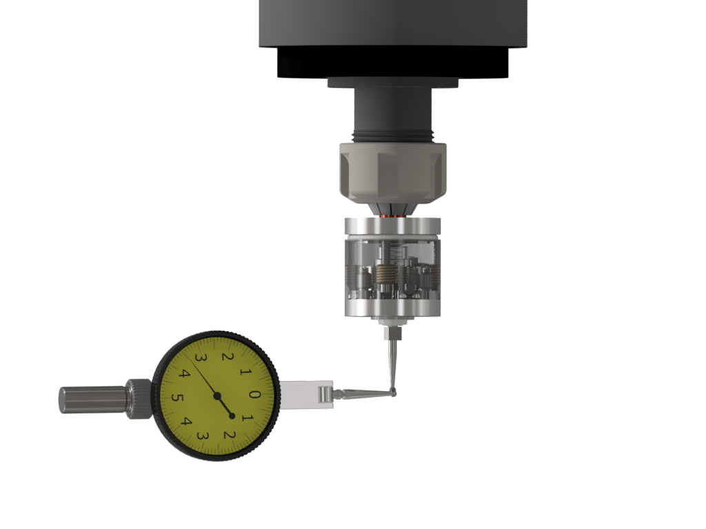
Fig.1
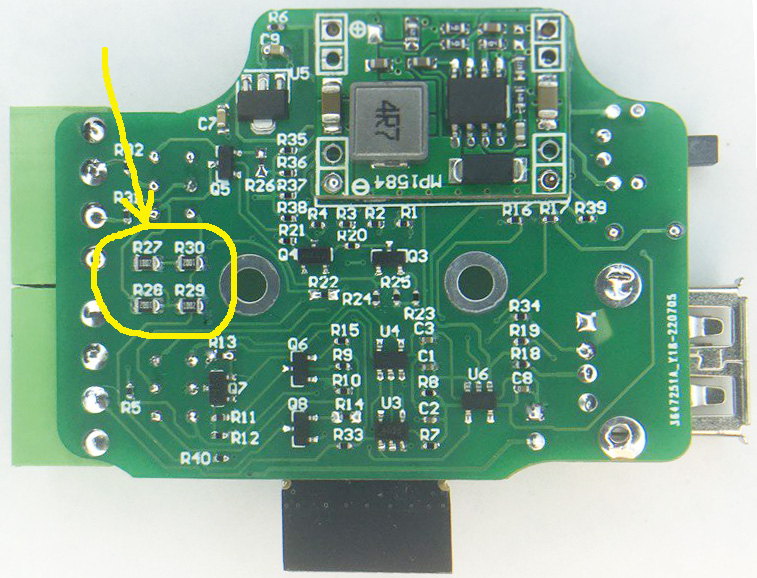
The deviation is eliminated by turning the adjusting screws M2.5 (the screws are recessed into the holes indicated by the green arrows in Fig. 2) with a 2mm hex key from the kit. When adjusting, both tightening and loosening of the screws are used.
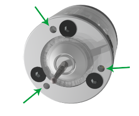
Fig.2
It is recommended to hold for a short lever of the key , so as not to develop excessive force (Fig. 3). It will be necessary to perform several cycles of spindle axis rotation--control-- adjustment in order to achieve a minimum deviation acceptable for a particular measurement.
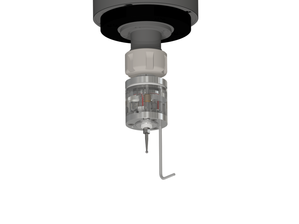
Fig.3
Using
The radio channel in Vers WLR simulates a normally closed connection between the probe and the receiver.
A broken radio channel is identical to a broken wire, with the only difference being that the response to a broken channel at the OUT or ERR outputs comes with a delay equal to the pool period (not to be confused with the delay in the response to pressing the stylus ~1.5 ms). The graph below shows speed-acceleration combinations that are safe for searching (area with green shading), at which the machine will stop without breaking the stylus, even if the radio communication fails at the most “unfortunate” moment when the probe touches the part. Over travel limit 4 mm and pool period of 0.3 s are taken into account.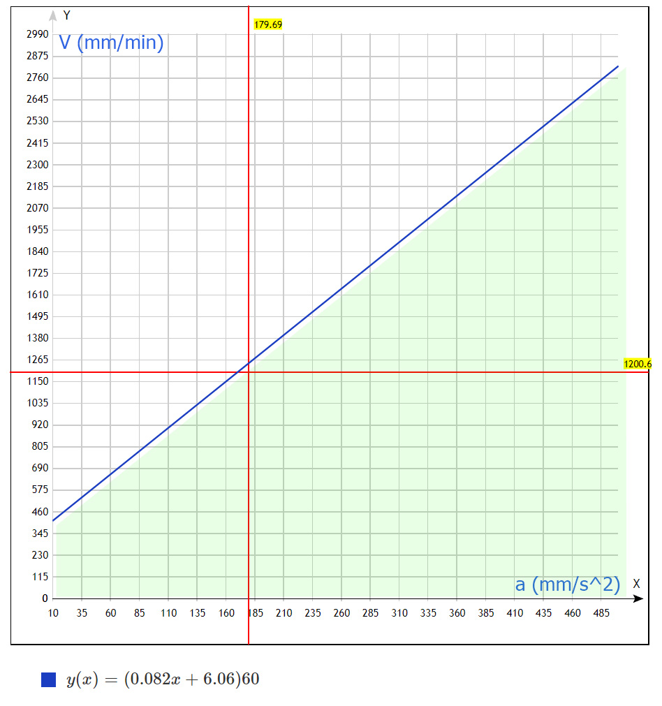
Formula is derived from initial conditions:
S = 4 mm permitted deviation stylus
t = 0.33c is the maximum delay time for detecting a broken connection, after this time it starts decelerating to a complete stop.
V - search speed in mm/min, Y axis on the graph
a - acceleration specified in the machine settings, in mm/c ^ 2, X axis on the graph
(Formula used: S = 2*V * t - a * (t ^ 2) / 2 )
There is software ProbeScreen in free access for convenient work with probe in the LinuxCNC
Probe Wizard - in the Mach3 system.